


5
FUNCTIONS
5.6 Response Delay Time
5 - 31
1
OVERVIEW
2
SYSTEM
CONFIGURATION
3
SPECIFICATIONS
4
PROCEDURES AND
SETTINGS BEFORE
OPERATION
5
FUNCTIONS
6
UTILITY PACKAGE (GX
Configurator-CT)
7
PROGRAMMING
8
TROUBLESHOOTING
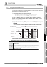
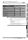
5.6 Response Delay Time
In the QD64D2, a response delays due to the cause indicated in (a) and (b) below.
(a) Scan time of the sequence program
It affects the delay of I/O signal.
Use the direct access input (DX) or the direct access output (DY) to minimize the
delay.
(b) Control cycle (1ms) of the QD64D2
Up to 2ms (1 control cycle 2) of delay occurs until the QD64D2 reads out the
output signal and buffer memory updated by the sequence program and
completes processing.
Update timing of the I/O signal and buffer memory varies within the range of a
control cycle.
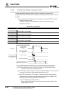
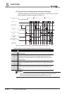
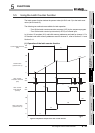
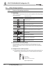
For example, the following is the maximum delay time until the QD64D2 executes the latch
counter function and updates the latch count value after the latch counter execution
command (Y07) is turned ON by the sequence program.
Maximum delay time [ms] = [Time of (a)] + [Maximum time of (b)]
= Sequence program scan time + 2 [ms]