


8
TROUBLESHOOTING
8.1 Error Processing and Recovery Methods
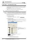
8.1.1 Checking error description using System Monitor of GX Developer
8 - 2
1
OVERVIEW
2
SYSTEM
CONFIGURATION
3
SPECIFICATIONS
4
PROCEDURES AND
SETTINGS BEFORE
OPERATION
5
FUNCTIONS
6
UTILITY PACKAGE (GX
Configurator-CT)
7
PROGRAMMING
8
TROUBLESHOOTING
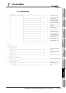
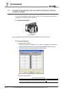
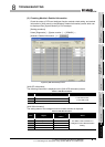
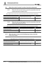
(3) Checking Module's Detailed Information
Check the status of LEDs and intelligent function module switch setting, and module
information in [H/W status] on the [Module's Detailed Information] screen which can
be displayed from [System Monitor] of GX Developer.
[Setting procedure]
Select [Diagnostics] [System monitor...] [QD64D2]
[Module's Detailed Information...]
Figure 8.2 [H/W Information] screen
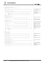
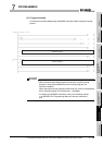
[H/W LED Information]
The following information is displayed on the [H/W LED Information] screen.
[H/W SW Information]
The setting status of the intelligent function module switches is displayed.
Table 8.1 H/W LED Information
Item Signal Value
RUN "RUN" LED on the QD64D2
0: The LED is OFF.
1: The LED is ON.
ERR "ERR." LED on the QD64D2
FUSE "FUSE" LED on the QD64D2
Table 8.2 H/W SW Information
Item Signal
Corresponding
switch
Value
CH1 CH1 setting Switch 1
For details, refer to Section 4.5
Intelligent Function Module Switch
Setting.
CH2 CH2 setting Switch 2
NOP1 ---- Switch 3
NOP2 ---- Switch 4
NOP3 ---- Switch 5