


5
FUNCTIONS
5.3 Using the Counter Value Comparison Function
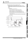
5.3.1 Using the coincidence output function
5 - 11
1
OVERVIEW
2
SYSTEM
CONFIGURATION
3
SPECIFICATIONS
4
PROCEDURES AND
SETTINGS BEFORE
OPERATION
5
FUNCTIONS
6
UTILITY PACKAGE (GX
Configurator-CT)
7
PROGRAMMING
8
TROUBLESHOOTING
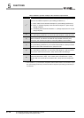
POINT
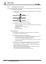
(1) At immediately after the power-on or resetting the programmable controller
CPU, the relation of the present value and the coincidence output point
setting is the following: "Present value = Coincidence output point setting = 0".
Therefore, the counter value coincidence (X02, X05, X12, and X15) of
channels that use the coincidence output function turns ON.
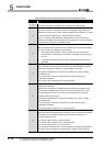
For channels that use the coincidence output function, always execute the
following procedures from 1 to 3.
For the programming method of the following procedures, refer to Section 7.3
and Section 7.4.
Procedure 1:
Set the following buffer memories and make sure that the coincidence output
point settings are other than "0"
Procedure 2:
Turn from OFF to ON then OFF the following signals to turn OFF the counter
value coincidence (X02, X05, X12, and X15).
Procedure 3 (Only for external output):
After checking that the counter value coincidence (X02, X05, X12, and X15) is
OFF, turn ON the coincidence output enable (Y03 and Y13).
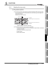
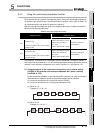
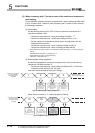
(2) Even if the coincidence signal No.1 reset command (Y01) is turned from ON
to OFF while the present value is equal to the coincidence output point
setting, the counter value coincidence (X02) and the coincidence output No.1
terminal (EQU1) turn ON again.
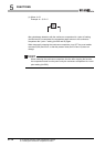
(3) When the counter value coincidence No.1 (X02) is turned from OFF to ON by
the coincidence detection process of the QD64D2, there may be cases where
the counter value large No.1 (X01) or the counter value small No.1 (X03)
turns ON.
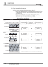
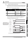
Buffer memory address to be set Setting value
CH1 coincidence output No.1 point setting (Un\G6 and 7)
Other than "0"
CH1 coincidence output No.2 point setting (Un\G8 and 9)
CH2 coincidence output No.1 point setting (Un\G206 and 207)
CH2 coincidence output No.2 point setting (Un\G208 and 209)
CH1 coincidence output No.1 point change request (Un\G10)
1
CH1 coincidence output No.2 point change request (Un\G11)
CH2 coincidence output No.1 point change request (Un\G210)
CH2 coincidence output No.2 point change request (Un\G211)
Signals to be turned OFF ON OFF
*1
CH1 coincidence signal No.1 reset command (Y01)
CH1 coincidence signal No.2 reset command (Y02)
CH2 coincidence signal No.1 reset command (Y11)
CH2 coincidence signal No.2 reset command (Y12)
*1 Make sure that ON time is longer than 2ms.