


4 - 12
4.5 Intelligent Function Module Switch Setting
4
PROCEDURES AND SETTINGS BEFORE
OPERATION
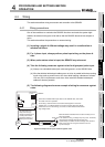
(3) Operating procedure
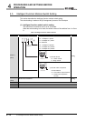
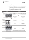
Set the switches on the [I/O assignment] screen of GX Developer.
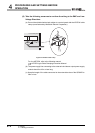
(a) [I/O assignment] screen
Make the following settings to the slot to which the QD64D2 is mounted.
[Type]: Select [Intelli].
[Model name]: Input the model of the module.
[Points]: Select [32points].
[Start XY]: Input the start I/O number of the QD64D2.
Figure 4.9 Setting example of [I/O assignment]
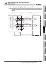
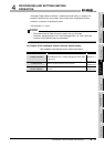
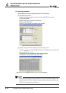
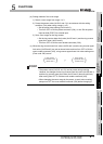
(b) [Switch setting for I/O and intelligent function module] screen
Click the on the [I/O assignment] screen to display the screen below and
set the switches from 1 to 5.
Entering the values in hexadecimal make the setting easier.
Change [Input format] to [HEX.] and enter values.
Figure 4.10 [Switch setting for I/O and intelligent function module] screen
POINT
Since [Error time output mode] and [H/W error time PLC operation mode] on the
[Switch setting for I/O and intelligent function module] screen are disabled to the
QD64D2, the settings are unnecessary.