


4 - 10
4.5 Intelligent Function Module Switch Setting
4
PROCEDURES AND SETTINGS BEFORE
OPERATION
4.5 Intelligent Function Module Switch Setting
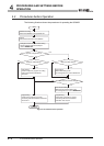
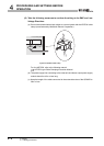
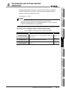
This section describes the intelligent function module switch setting.
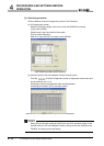
The switch setting is made on the [I/O assignment] screen of GX Developer.
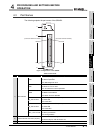
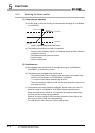
(1) Intelligent function module switch setting
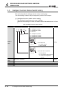
The switch has five switches and is set at 16-bit data.
When the switch setting is not made, the default values of the switches from 1 to 5 are
0.
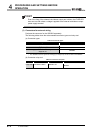
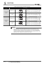
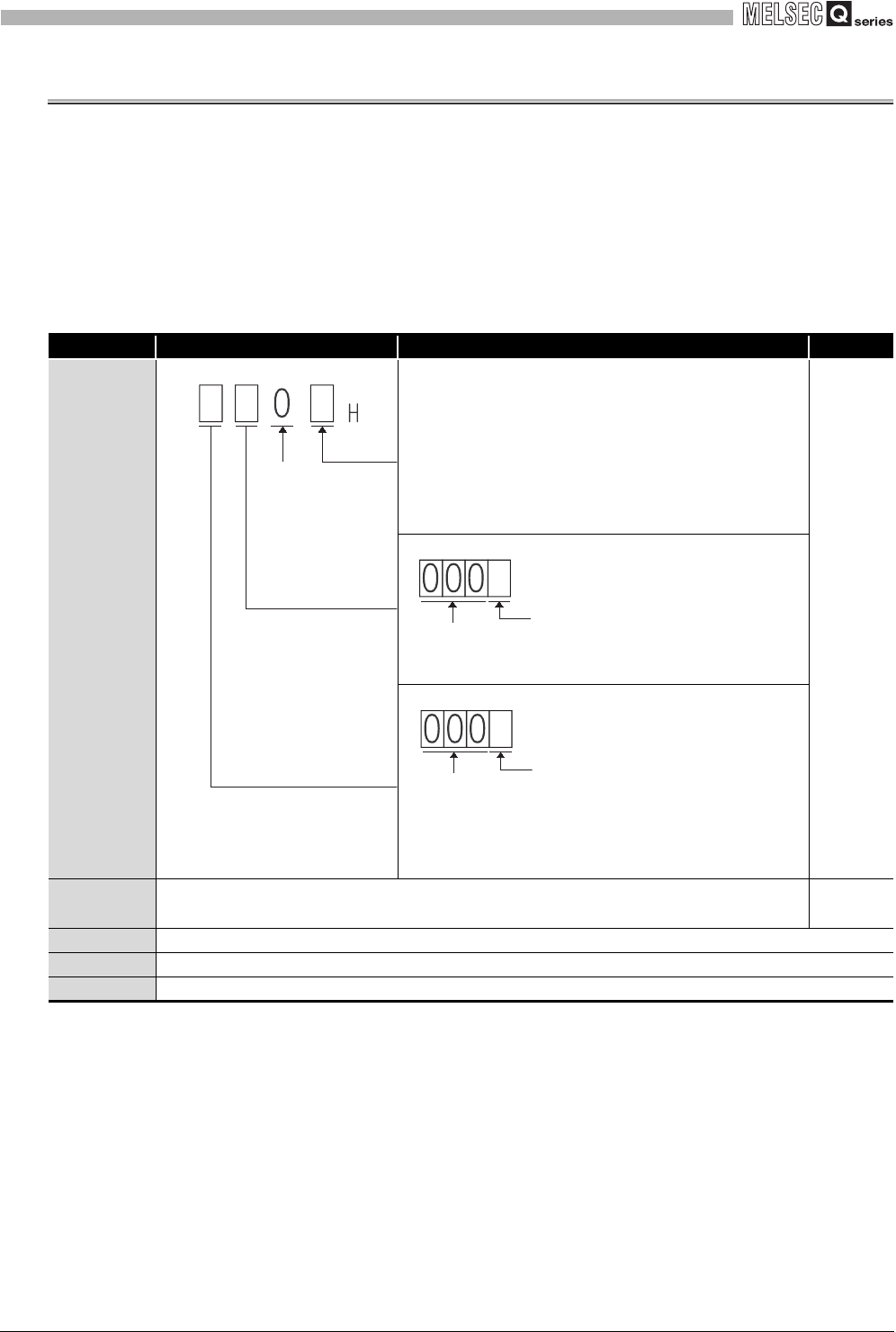
Table 4.5 Intelligent function module switches
Setting item Setting value Default
Switch 1
(CH1)
1) Pulse input mode
0
H: 1 multiple of 1 phase
1H: 2 multiples of 1 phase
2H: CW/CCW
3H: 1 multiple of 2 phases
4
H: 2 multiples of 2 phases
5H: 4 multiples of 2 phases
0000
H
2) Counter format
0H : Linear counter
1H : Ring counter
3) Counter value comparison
function election
0
H : Coincidence output function
1H : Continuous comparison
function
Switch 2
(CH2)
Same as for the switch 1 0000
H
Switch 3 Reserved: Fixed to 0
Switch 4 Reserved: Fixed to 0
Switch 5 Reserved: Fixed to 0
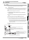
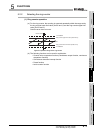
1)
Reserved:
Fixed to 0
2)
b8b11
Reserved:
Fixed to 0
3)
b12b15
Reserved:
Fixed to 0