


7 - 5
7.2 For Use in Normal System Configuration
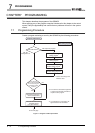
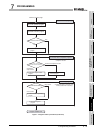
7.2.1 Before creating a program
7
PROGRAMMING
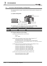
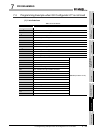
(2) Intelligent function module switch setting
Based on the setting conditions given in Section 7.2 (2), make the intelligent function
module switch settings.
(a) Each switch setting
1) Switch 1: CH1 setting
2) Switch 2: CH2 setting
3) Switch 3, switch 4, switch 5: Use prohibited (0: fixed)
* If any other than 0 is set to the switches from 1 to 5 where 0 is fixed, the functions of the QD64D2
are not guaranteed.
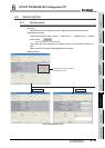
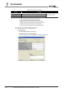
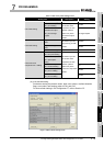
(b) Write the settings in (a) to the QD64D2.
On GX Developer's "Parameter setting" screen, select the "I/O assignment" tab,
click "Switch setting", and make settings of Switch 1 to 5 on the screen shown
below.
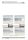
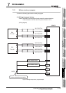
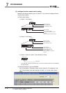
H
0002
CH1: 2H (CW/CCW)
00000000
b9b10b11b12b13b14 b8b15
<Switch 1>
Pulse input mode
Use prohibited (0: fixed*)
Counter format
CH1: 0 (Linear counter)
Counter value comparison function
selection
CH1: 0 (Coincidence output function)
0: fixed*
0: fixed*
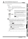
H
1102
CH2: 2H (CW/CCW)
00010001
b9b10b11b12b13b14 b8b15
<Switch 2>
Pulse input mode
Use prohibited (0: fixed*)
Counter format
CH2: 1 (Ring counter)
Counter value comparison
function selection
CH2: 1 (Continuous comparison
function)
0: fixed*
0: fixed*
H
Fixed at 0
0000
<Switch 3 to 5>