


3
SPECIFICATIONS
3.5 Specifications of I/O Interfaces with External Device
3.5.4 Interface for external device
3 - 27
1
OVERVIEW
2
SYSTEM
CONFIGURATION
3
SPECIFICATIONS
4
PROCEDURES AND
SETTINGS BEFORE
OPERATION
5
FUNCTIONS
6
UTILITY PACKAGE (GX
Configurator-CT)
7
PROGRAMMING
8
TROUBLESHOOTING
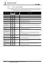
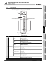
3.5.4 Interface for external device
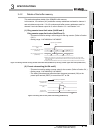
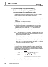
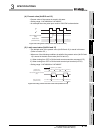
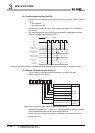
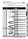
The following table shows the list of external device interface of the QD64D2.
Table 3.10 List of external device interface of the QD64D2
I/O
classification
Internal circuit
Terminal
number Signal name
CH1 CH2
Input
B19 A19 Phase A pulse input +
B18 A18 Phase A pulse input -
B17 A17 Phase B pulse input +
B16 A16 Phase B pulse input -
B15, A15 Pulse input common
B12 A12 Preset input 24V
B13 A13 Preset input common
B08 A08 Latch counter input 24V
B09 A09 Latch counter input common
Output
B05 A05 Coincidence output No.1
B04 A04 Coincidence output No.2
B03, A03
External coincidence output power supply
12/24V
B02, A02
External coincidence output power supply
GND (0V)
+5V
27k
1/10W
27k
1/10W
4.7k
1/10W
100
1/2W
4.7k
1/10W
+5V
Isolator
(Isolating
element)
Line
receiver
+5V
27k
1/10W
27k
1/10W
4.7k
1/10W
100
1/2W
4.7k
1/10W
+5V
Isolator
(Isolating
element)
Line
receiver
10k
1/3W
1k
1/10W
10k
1/3W
1k
1/10W
FUSE
To blown fuse
detection circuit