


3 - 22
3.4 Buffer Memory Assignment
3.4.2 Details of the buffer memory
3
SPECIFICATIONS
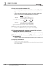
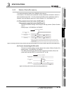
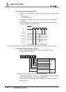
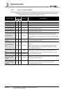
(6) Overflow detection flag (Un\G16)
• Overflow occurrence status of the counter is stored in this area. (Refer to Section
5.2.1.)
0: No detection
1: Overflow occurred
• Overflow occurs when the count value exceeds the range of -2147483648 to
2147483647.
• The overflow detection flag (Un\G16) can be cleared by the preset command
(Y04) or the preset input terminal (PRST).
Figure 3.23 Timing chart for the overflow detection flag (Un\G16) (when the pulse input mode is 1 multiple of 1 phase)
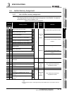
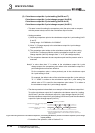
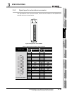
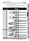
(7) External I/O status monitor (Un\G17)
• The I/O status of the external device connector is stored in this area.
• Storage contents is as follows.
Figure 3.24 Storage contents of the external I/O status monitor (Un\G17)
• Storage item marked with "*1" turns to "1" (ON) regardless of applying a voltage
to the external coincidence output power supply terminal.
• It takes up to 2ms until actual I/O status is reflected to the external I/O status
monitor (Un\G17).
2
A
B
2147483646 2147483647
0
0
0
0
0 100
ON
1
1
Operation by the QD64D2
Present value
(Un\G12 and 13)
Overflow detection flag
(Un\G16)
Preset value setting
(Un\G4 and 5)
Preset command
(Y04)
Error code
(Un\G18)
0:OFF
1:ON
b15 b8b7 b0
00
0000000
Reserved: Fixed to 0
Storage item
Definition
Preset input status
Latch counter input status
Phase A input status
Phase B input status
Coincidence output No.1 output status *1
Coincidence output No.2 output status *1
Addition/subtraction status
0: During addition
1: During
subtraction