


3
SPECIFICATIONS
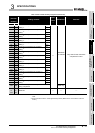
3.4 Buffer Memory Assignment
3.4.2 Details of the buffer memory
3 - 21
1
OVERVIEW
2
SYSTEM
CONFIGURATION
3
SPECIFICATIONS
4
PROCEDURES AND
SETTINGS BEFORE
OPERATION
5
FUNCTIONS
6
UTILITY PACKAGE (GX
Configurator-CT)
7
PROGRAMMING
8
TROUBLESHOOTING
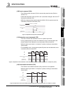
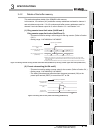
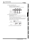
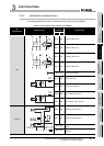
(4) Present value (Un\G12 and 13)
• Present value of the counter is stored in this area.
• Setting range: -2147483648 to 2147483647
• An example when the pulse input mode is CW/CCW is shown below.
Figure 3.21 Timing chart of the present value (Un\G12 and 13)
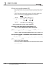
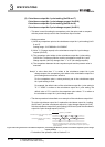
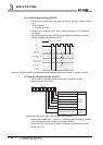
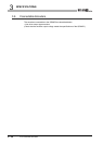
(5) Latch count value (Un\G14 and 15)
• The latched value of the present value (Un\G12 and 13) is stored in this area.
(Refer to Section 5.5.)
• When one of the following conditions is satisfied, the present value (Un\G12 and
13) is stored in the latch count value (Un\G14 and 15).
1) When turning from OFF to ON the latch counter execution command (Y07)
2) When turning from OFF to ON the latch counter input terminal (LATCH)
• Setting range: -2147483648 to 2147483647
Figure 3.22 Timing chart for the latch count value (Un\G14 and 15)
A
B
ON
210
Count enable command
(Y06)
Present value
(Un\G12 and 13)
031
04123
* t 2ms
t* t*
Operation by the QD64D2
Present value
(Un\G12 and 13)
Latch counter execution command
(Y07)
Latch count value
(Un\G14 and 15)