


3
SPECIFICATIONS
3.1 Performance Specifications
3.1.2 Derating chart
3 - 3
1
OVERVIEW
2
SYSTEM
CONFIGURATION
3
SPECIFICATIONS
4
PROCEDURES AND
SETTINGS BEFORE
OPERATION
5
FUNCTIONS
6
UTILITY PACKAGE (GX
Configurator-CT)
7
PROGRAMMING
8
TROUBLESHOOTING
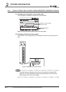
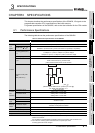
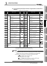
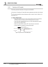
3.1.2 Derating chart
Figure 3.4 Derating chart
This section explains conditions for each counter value comparison function selection.
(1) When all channels are the coincidence output function
Take care so that the ratio of the number of points that external coincidence output
(ON) is executed to the number of external coincidence output points of the module (4
points) does not exceed the ON ratio in Figure 3.4.
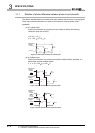
(2) When all channels are the continuous comparison function
Take care so that the ratio of continuous comparison No. m ON time setting (Un\G52,
Un\G102) (t1) to the time from start of coincidence output to the next coincidence
output (t2) in Figure 3.5 may not exceed the ON ratio in Figure 3.4.
(For interval of the continuous comparison No. m point n setting that decides t2, refer
to Section 5.3.2.)
Figure 3.5 Relationship between ON time setting in the case of the continuous comparison function (t1) and the time from start of
coincidence output to the next coincidence output (t2)
40
50
60
70
80
90
100
0 1020304050
Ambient temperature( )
ON ratio (%)
55
100 [%]
ON ratio [%]
The number of points that
external coincidence output
(ON) is executed
4 (point)
ON ratio [%]
100 [%]
t1[ms]
t2[ms]
ON
OFF
t1
t2
Coincidence output No. m terminal
t1