


2
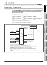
SYSTEM CONFIGURATION
2.1 Applicable Systems
2 - 2
1
OVERVIEW
2
SYSTEM
CONFIGURATION
3
SPECIFICATIONS
4
PROCEDURES AND
SETTINGS BEFORE
OPERATION
5
FUNCTIONS
6
UTILITY PACKAGE (GX
Configurator-CT)
7
PROGRAMMING
8
TROUBLESHOOTING
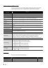
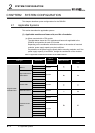
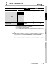
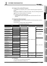
: Applicable : N/A
* 1 Limited within the range of I/O points for the CPU module.
* 2 Can be installed to any I/O slot of a base unit.
* 3 For the coincidence detection interrupt function, use the Basic model QCPU of function version B
or later.
* 4 The coincidence detection interrupt function is not supported.
* 5 Connection of extension base units is not available with any safety CPU.
Remark
For the use of the C Controller module, refer to C Controller Module User's
Manual.
Programmable
controller CPU
Universal model
QCPU
Q03UDECPU
Up to 64
Q04UDEHCPU
Q06UDEHCPU
Q10UDEHCPU
Q13UDEHCPU
Q20UDEHCPU
Q26UDEHCPU
Q50UDEHCPU
Q100UDEHCPU
Safety CPU QS001CPU N/A
*5
C Controller module
Q06CCPU-V
Up to 64
Q06CCPU-V-B
Q12DCCPU-V
Table 2.1 Applicable modules and the number of mountable modules (Continued)
Applicable CPU module
No. of
modules
*1
Base unit
*2
CPU type CPU model Main base unit
Extension base
unit