


3 - 2
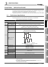
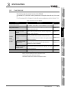
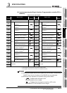
3.1 Performance Specifications
3.1.1 Relation of phase difference between phase A and phase B
3
SPECIFICATIONS
3.1.1 Relation of phase difference between phase A and phase B
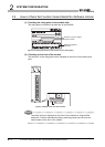
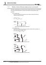
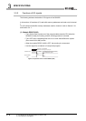
The relation indicated below is for each pulse input mode at the maximum counting speed.
Pulse input waveform that does not reach to the maximum counting speed is also
applicable.
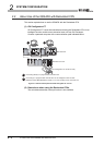
(a) At 1-phase input
Pulse input waveform at 1-phase input input needs to satisfy the following
conditions (duty ratio of 50%).
t (=t
H+tL) = 1.0 s
t
H, tL = 0.5 s (= 0.5 t)
Figure 3.1 Pulse input waveform at 1-phase input
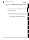
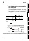
(b) At 2-phase input
Pulse input waveform at 2-phase input needs to satisfy both the condition at 1-
phase input and the condition below.
t
1, t2, t3, t4 = 0.25 s (= 0.25 t)
Figure 3.2 Pulse input waveform at 2-phase input 1
Figure 3.3 Pulse input waveform at 2-phase input 2
0.1V
0.1V
-0.1V
t
t
H
t
L
Differential
voltage
H level
L level
0.1V
t1
0.1V
0.1V
-0.1V
0.1V -0.1V
t2
Differential
voltage
H level
L level
Differential
voltage
H level
L level
A
B
t3
-0.1V 0.1V
0.1V -0.1V
t4
0.1V
-0.1V
Differential
voltage
H level
L level
Differential
voltage
H level
L level
B
A