


S3C84E5/C84E9/P84E9 CONTROL REGISTER
4-39
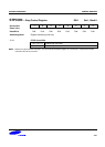
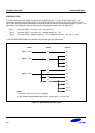
NOTES:
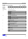
1. In mode 2, if the MCE (UARTCON.5) bit is set to "1", then the receive interrupt will not be activated if the received
9th data bit is "0". In mode 1, if MCE = "1”, then the receive interrupt will not be activated if a valid stop bit was not
received. In mode 0, the MCE (UARTCON.5) bit should be "0".
2. The descriptions for 8-bit and 9-bit UART mode do not include start and stop bits for serial data receive and transmit.
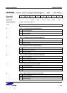
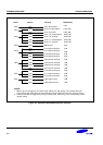
3. Parity enable bits, PEN, are located in the UARTPND register at address F4H, bank 0.
4. Parity enable and parity error check can be available in 9-bit UART mode (Mode 2) only.