


S3C84E5/C84E9/P84E9 UART
13-9
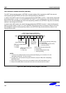
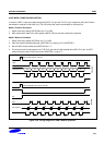
UART MODE 0 FUNCTION DESCRIPTION
In mode 0, UART is input and output through the RxD (P1.4) pin and TxD (P1.5) pin outputs the shift clock. Data is
transmitted or received in 8-bit units only. The LSB of the 8-bit value is transmitted (or received) first.
Mode 0 Transmit Procedure
1. Select mode 0 by setting UARTCON.6 and .7 to "00B".
2. Write transmission data to the shift register UDATA (F5H) to start the transmission operation.
Mode 0 Receive Procedure
1. Select mode 0 by setting UATCON.6 and .7 to "00B".
2. Clear the receive interrupt pending bit (UARTPND.1) by writing a "0" to UARTPND.1.
3. Set the UART receive enable bit (UARTCON.4) to "1".
4. The shift clock will now be output to the TxD (P1.5) pin and will read the data at the RxD (P1.4) pin. A UART
receive interrupt (vector E4H) occurs when UARTCON.1 is set to "1".
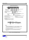
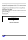
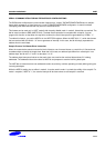
Transmit
D0 D1 D2 D3 D4 D5 D6 D7
Write to Shift Register (UDATA)
RxD (Data Out)
TxD (Shift Clock)
TIP
Shift
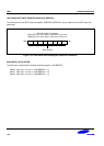
Receive
Write to UARTPND (Clear RIP and set RE)
Shift
D0 D1 D2 D3 D4 D5 D6 D7
TxD (Shift Clock)
RxD (Data In)
RE
RIP
1 2 3 4 5 6 7 8
Figure 13-6. Timing Diagram for UART Mode 0 Operation