BASIC TIMER S3C84E5/C84E9/P84E9
10-4
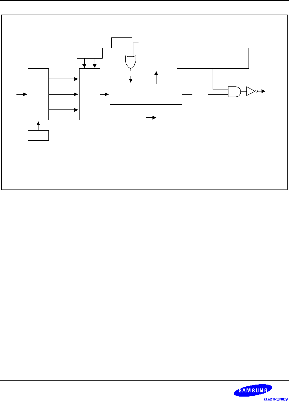
NOTE:
During a power-on reset operation, the CPU is idle during the required oscillation
stabilization interval (until bit 4 of the basic timer counter overflows).
MUX
fxx/4096
DIV
fxx/1024
fxx/128
fxx
Bits 3, 2
Bit 0
Basic Timer Control Register
(Write '1010xxxxB' to disable)
Clear
Bit 1 RESET or STOP
Data Bus
8-Bit Up Counter
(BTCNT, Read-Only)
Start the CPU
(note)
OVF
RESET
R
Figure 10-2. Basic Timer Block Diagram


