


S3C84E5/C84E9/P84E9 UART
13-5
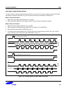
In mode 2 (9-bit UART data), by setting the parity enable bit (PEN) of UARTPND register to '1', the 9
th
data bit of
transmit data will be an automatically generated parity bit. Also, the 9
th
data bit of the received data will be treated as
a parity bit for checking the received data.
In parity enable mode (PEN = 1), UARTCON.3 (TB8) and UARTCON.2 (RB8) will be a parity selection bit for transmit
and receive data respectively. The UARTCON.3 (TB8) is for settings of the even parity generation (TB8 = 0) or the
odd parity generation (TB8 = 0) in the transmit mode. The UARTCON.2 (RB8) is also for settings of the even parity
checking (RB8= 0) or the odd parity checking (RB8 =1) in the receive mode. The parity enable (generation/checking)
functions are not available in UART mode 0 and 1.
If you don’t want to use a parity mode, UARTCON.2 (RB8) and UARTCON.3 (TB8) are a normal control bit as the 9
th
data bit, in this case, PEN must be disable (“0”) in mode 2. Also it is needed to select the 9th data bit to be
transmitted by writing TB8 to "0" or "1".
The receive parity error flag (RPE) will be set to ‘0’ or ‘1’ depending on parity error whenever the 8
th
data bit of the
receive data has been shifted.
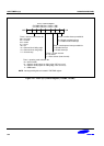
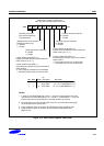
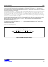
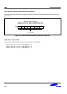
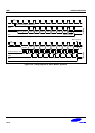
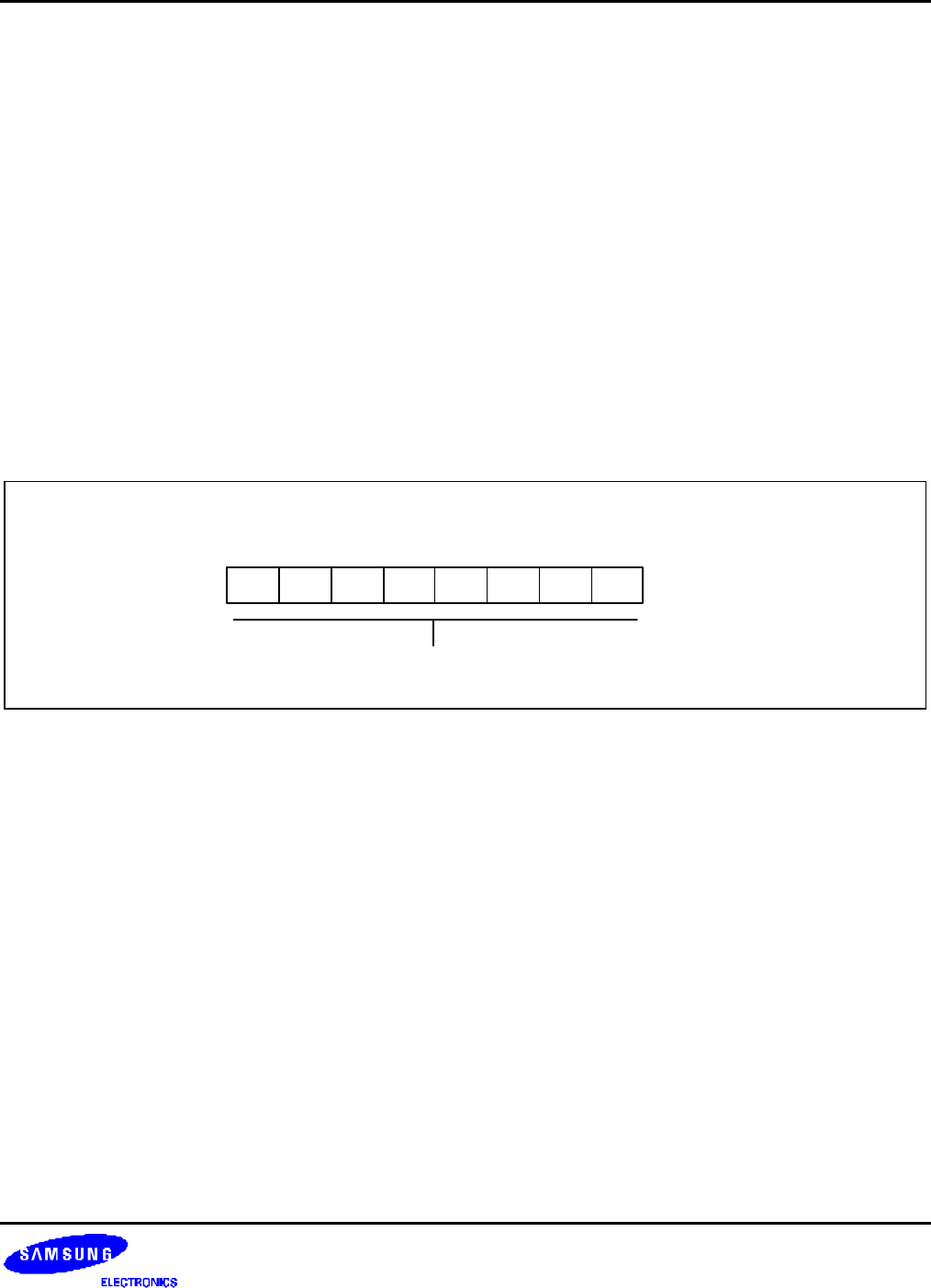
UART DATA REGISTER (UDATA)
UART Data Register (UDATA)
F5H, Set1, Bank 0, R/W, Reset Value: FFH
MSB LSB.5
.4 .1 .0.7 .6 .3 .2
Transmit or Receive data
Figure 13-3. UART Data Register (UDATA)