


A/D CONVERTER S3C84E5/C84E9/P84E9
15-2
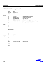
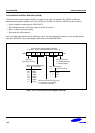
A/D CONVERTER CONTROL REGISTER (ADCON)
The A/D converter control register, ADCON, is located in set1, bank 0 at address F7H. ADCON is read-write
addressable using 8-bit instructions only. But, the EOC bit, ADCON.3 is read only. ADCON has four functions:
— Bits 6–4 select an analog input pin (ADC0–ADC7).
— Bit 3 indicates the end of conversion status of the A/D conversion.
— Bits 2–1 select a conversion speed.
— Bit 0 starts the A/D conversion.
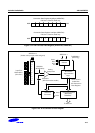
Only one analog input channel can be selected at a time. You can dynamically select any one of the eight analog
input pins, ADC0–ADC7 by manipulating the 3-bit value for ADCON.6–ADCON.4
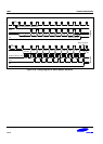
Start or Enable bit
0 = Disable Operation
1 = Start Operation
A/D Converter Control Register (ADCON)
F7H, Set 1, Bank 0, R/W (ADCON.3 bit is read-only)
.7 .6 .5 .4 .3 .2 .1 .0MSB LSB
End-of-Conversion bit (realy only):
0 = Conversion not complete
1 = Conversion complete
A/D Input Pin Selection bits:
A/D Input pin
Clock Selection bit:
.4.5
000
001
010
011
100
101
110
111
ADC0
ADC1
ADC2
ADC3
ADC4
ADC5
ADC6
ADC7
Conversion Clock.1.2
0
1
0
1
0
0
1
1
fxx/16
fxx/8
fxx/4
fxx
.6
Not used
(must keep always 0)
Figure 15-1. A/D Converter Control Register (ADCON)