


S3C84E5/C84E9/P84E9 UART
13-11
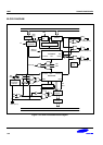
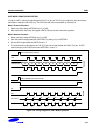
UART MODE 2 FUNCTION DESCRIPTION
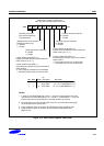
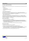
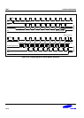
In mode 2, 11-bits are transmitted (through the TxD pin) or received (through the RxD pin). Each data frame has four
components:
— Start bit ("0")
— 8 data bits (LSB first)
— Programmable 9th data bit or parity bit
— Stop bit ("1")
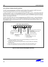
< In parity disable mode (PEN = 0) >
The 9th data bit to be transmitted can be assigned a value of "0" or "1" by writing the TB8 bit (UARTCON.3).
When receiving, the 9th data bit that is received is written to the RB8 bit (UARTCON.2), while the stop bit is ignored.
The baud rate for mode 2 is fosc/(16 x (16-bit BRDATA + 1)) clock frequency.
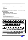
< In parity enable mode (PEN = 1) >
The 9th data bit to be transmitted can be an automatically generated parity of "0" or "1" depending on a parity
generation by means of TB8 bit (UARTCON.3). When receiving, the received 9th data bit is treated as a parity for
checking receive data by means of the RB8 bit (UARTCON.2), while the stop bit is ignored. The baud rate for mode
2 is fosc/(16 x (16-bit BRDATA + 1)) clock frequency.
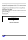
Mode 2 Transmit Procedure
1. Select the baud rate generated by 16-bit BRDATA.
2. Select mode 2 (9-bit UART) by setting UARTCON bits 6 and 7 to '10B'. Also, select the 9th data bit to be
transmitted by writing TB8 to "0" or "1" and set PEN bit of UARTPND register to “0” if you don’t use a parity
mode. If you want to use the parity enable mode, select the parity bit to be transmitted by writing TB8 to "0" or
"1" and set PEN bit of UARTPND register to “1”.
3. Write transmission data to the shift register, UDATA (F5H), to start the transmit operation.
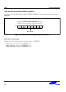
Mode 2 Receive Procedure
1. Select the baud rate to be generated by 16-bit BRDATA.
2. Select mode 2 and set the receive enable bit (RE) in the UARTCON register to "1".
3. If you don’t use a parity mode, set PEN bit of UARTPND register to “0” to disable parity mode.
If you want to use the parity enable mode, select the parity type to be check by writing TB8 to "0" or "1" and set
PEN bit of UARTPND register to “1”. Only 8 bits (Bit0 to Bit7) of received data are available for data value.
4. The receive operation starts when the signal at the RxD pin goes to low level.