


I/O PORTS S3C84E5/C84E9/P84E9
9-14
PORT 4
Port 4 is a 6-bit I/O port that you can use two ways:
— General-purpose digital I/O
— Alternative function: INT8– INT10, TBPWM
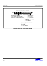
Port 4 is accessed directly by writing or reading the port 4 data register, P4 at location E4H in set 1, bank 0.
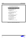
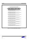
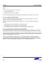
Port 4 Control Register (P4CONH, P4CONL)
Port 4 pins are configured individually by bit-pair settings in two control registers located in set 1, bank 0:
P4CONL (low byte, F1H) and P4CONH (high byte, F0H).
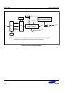
When you select output mode, a push-pull circuit is configured. In input mode, three different selections are
available:
— Schmitt trigger input and interrupt generation on falling signal edges.
— Schmitt trigger input and interrupt generation on rising signal edges.
— Schmitt trigger input with pull up resister and interrupt generation on falling signal edges.
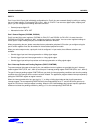
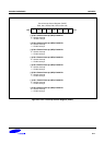
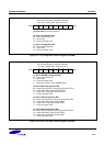
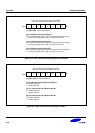
Port 4 Interrupt Enable and Pending Registers (P4INT, P4INTPND)
To process external interrupts at the port 4 pins, two additional control registers are provided: the port 4 interrupt
enable register P4INT (F2H, set 1, bank 0) and the port 4 interrupt pending register P4INTPND (F3H, set 1, bank 0).
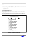
The port 4 interrupt pending register P4INTPND lets you check for interrupt pending conditions and clear the pending
condition when the interrupt service routine has been initiated. The application program detects interrupt requests by
polling the P4INTPND register at regular intervals.
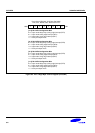
When the interrupt enable bit of any port 4 pin is “1”, a rising or falling signal edge at that pin will generate an
interrupt request. The corresponding P4INTPND bit is then automatically set to “1” and the IRQ level goes low to
signal the CPU that an interrupt request is waiting. When the CPU acknowledges the interrupt request, application
software must clear the pending condition by writing a “0” to the corresponding P4INTPND bit.