


S3C84E5/C84E9/P84E9 CLOCK CIRCUIT
7-1
7 CLOCK CIRCUIT
OVERVIEW
The clock frequency generated for the Main clock of S3C84E5/C84E9/P84E9 by an external crystal can range from
1 MHz to 12 MHz. The maximum CPU clock frequency is 12 MHz. The XIN and XOUT pins connect the external
oscillator or clock source to the on-chip clock circuit. Also the subsystem clock frequency for the Watch timer by an
external crystal can range from 30 kHz to 35 kHz. The XTIN and XTOUT pins connect the external oscillator or clock
source to the on-chip clock circuit. The sub-system oscillation pins, XTIN and XTOUT can be used for normal digital
I/O pins (P0.0, P0.1) if they are not used for oscillation pins.
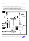
SYSTEM CLOCK CIRCUIT
The system clock circuit has the following components:
— External crystal or ceramic resonator oscillation source (or an external clock source)
— Oscillator stop and wake-up functions
— Programmable frequency divider for the CPU clock (fxx divided by 1, 2, 8, or 16)
— System clock control register, CLKCON
— Oscillator control register, OSCCON and STOP control register, STPCON
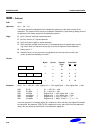
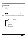
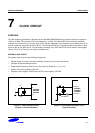
X
IN
X
OUT
C1
C2
S3C84E5
S3C84E9
S3P84E9
Figure 7-1. Main Oscillator Circuit
(Crystal or Ceramic Oscillator)
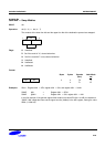
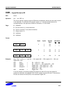
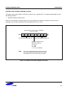
XT
IN
/P0.0
XT
OUT
/P0.1
32.768 kHz
S3C84E5
S3C84E9
S3P84E9
Figure 7-2. Sub-System Oscillator Circuit
(Crystal Oscillator)