


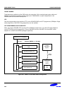

S3C84E5/C84E9/P84E9 DEVELOPMENT TOOLS
20-5
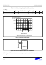
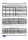
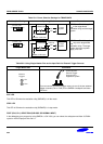
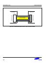
Table 20-3. The Port 0.0 and Port 0.1 selection setting
“Sub-OSC” Setting Description
XTin
P0.0
XTout
P0.1
If you set the Sub-OSC to the XTin and XTout side,
32,768Hz-subsystem crystal will be connected to P0.0
and P0.1 pins, and these pins are isolated to the user
system.
XTin
P0.0
XTout
P0.1
If you set the Sub-OSC to the P0.0 and P0.1 side,
32,768Hz-subsystem crystal will be disconnected to
P0.0 and P0.1 pins, and these pins are connected to
the user system through J101.
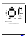
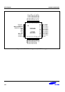
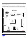
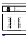
1
3
5
7
9
11
J101
44-PIN DIP SOCKET
13
15
17
19
21
23
25
27
29
31
33
35
37
39
41
43
20
22
24
26
28
30
32
34
36
38
40
42
44
10
12
14
16
18
2
4
6
8
XTin/P0.0
INT10/P4.2
VSS
XIN
P4.1/INT9
nRESET
P2.1/INT1
P2.3/INT3
P2.5/INT5
P2.7/INT7
AVREF
P3.0/ADC0
P3.2/ADC2
P3.4/ADC4
P3.6/ADC6
P1.5/TXD
P1.3/BZOUT
P1.1/T1CK0
P0.7/TACAP
P0.5/T1CAP0
P0.3/T1CK1
P4.4
XTout/P0.1
TBPWM/P4.3
VDD
XOUT
TEST
P4.0/INT8
INT0/P2.0
INT2/P2.2
INT4/P2.4
INT6/P2.6
P4.5
AVSS
P3.1/ADC1
P3.3/ADC3
P3.5/ADC5
P3.7/ADC7
P1.4/RXD
P1.2/T1OUT0
P1.0/TAOUT
TACK/P0.6
T1OUT1/P0.4
T1CAP1/P0.2
Figure 20-3. 44-Pin Connector Pin Assignment for TB84E5/84E9