


DEVELOPMENT TOOLS S3C84E5/C84E9/P84E9
20-4
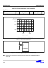
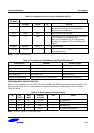
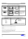
Table 20-1. Power Selection Settings for TB84E5/84E9
To User_Vcc' Settings Operating Mode Comments
To User_V
DD
Off On
Target
System
SMDS2+ or SK-1000
TB84E5/E9
V
DD
V
SS
V
DD
SMDS2+ or SK-1000 supplies
V
DD
to the target board
(evaluation chip) and the target
system.
To User_V
DD
Off On
Target
System
SMDS2+ or SK-1000
TB84E5/E9
External
V
DD
V
SS
V
DD
SMDS2+ or SK-1000 supplies
V
DD
only to the target board
(evaluation chip). The target
system must have a power
supply of its own.
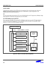
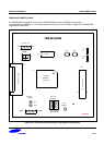
Table 20-2. Using Single Header Pins as the Input Path for External Trigger Sources
Target Board Part Comments
External
Triggers
Ch1
Ch2
Connector from
External Trigger
Sources of the
Application System
You can connect an external trigger source to one of the two external
trigger channels (CH1 or CH2) for the SMDS2+ breakpoint and trace
functions.
IDLE LED
This LED is ON when the evaluation chip (S3E84E0) is in idle mode.
STOP LED
This LED is ON when the evaluation chip (S3E84E0) is in stop mode.
PORT (P0.0, P0.1) SELECTION (SUB-OSC OR NORMAL INPUT)
In the debugging your program by using SMDS2+ or SK-1000, you can select the subsystem oscillator 32,768Hz
crystal or normal input port 0.0 and 0.1.