


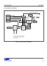

S3C84E5/C84E9/P84E9 UART
13-13
SERIAL COMMUNICATION FOR MULTIPROCESSOR CONFIGURATIONS
The S3C9-series multiprocessor communication features let a "master" S3C84E5/C84E9/P84E9 send a multiple-
frame serial message to a "slave" device in a multi- S3C84E5/C84E9/P84E9 configuration. It does this without
interrupting other slave devices that may be on the same serial line.
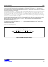
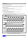
This feature can be used only in UART mode 2 with the parity disable mode. In mode 2, 9 data bits are received. The
9th bit value is written to RB8 (UARTCON.2). The data receive operation is concluded with a stop bit. You can
program this function so that when the stop bit is received, the serial interrupt will be generated only if RB8 = "1".
To enable this feature, you set the MCE bit in the UARTCON registers. When the MCE bit is "1", serial data frames
that are received with the 9th bit = "0" do not generate an interrupt. In this case, the 9th bit simply separates the
address from the serial data.
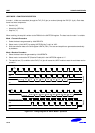
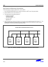
Sample Protocol for Master/Slave Interaction
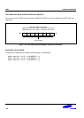
When the master device wants to transmit a block of data to one of several slaves on a serial line, it first sends out
an address byte to identify the target slave. Note that in this case, an address byte differs from a data byte: In an
address byte, the 9th bit is "1" and in a data byte, it is "0".
The address byte interrupts all slaves so that each slave can examine the received byte and see if it is being
addressed. The addressed slave then clears its MCE bit and prepares to receive incoming data bytes.
The MCE bits of slaves that were not addressed remain set, and they continue operating normally while ignoring the
incoming data bytes.
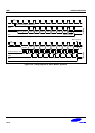
While the MCE bit setting has no effect in mode 0, it can be used in mode 1 to check the validity of the stop bit. For
mode 1 reception, if MCE is "1", the receive interrupt will be issue unless a valid stop bit is received.