


S3C84E5/C84E9/P84E9 I/O PORTS
9-15
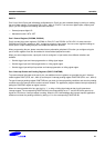
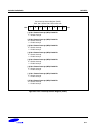
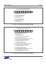
Port 4 Control Register, High Byte (P4CONH)
F0H, Set1, Bank0, R/W, Reset value="00"
.7 .6 .5 .4 .3 .2 .1 .0MSB LSB
[.7-.4] Not used
(must keep always 0)
[.3-.2] P4.5 Configuration Bits
0 0 = Input mode with pull-up
0 1 = Input mode
1 X = Push-pull output mode
[.1-.0] P4.4 Configuration Bits
0 0 = Input mode with pull-up
0 1 = Input mode
1 X = Push-pull output mode
Figure 9-11. Port 4 High-Byte Control Register (P4CONH)
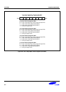
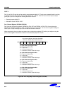
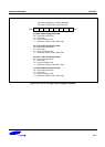
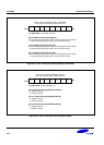
Port 4 Control Register, Low Byte (P4CONL)
F1H, Set1, Bank0, R/W, Reset value="00"
.7 .6 .5 .4 .3 .2 .1 .0MSB LSB
[.7-.6] P4.3/TBPWM Configuration Bits
0 0 = Input mode with pull-up
0 1 = Input mode
1 0 = Push-pull output mode
1 1 = Alternative function mode: TBPWM output
[.5-.4] P4.2/INT10 Configuration Bits
0 0 = Input mode with pull-up; falling edge interrupt (INT10)
0 1 = Input mode; falling edge interrupt (INT10)
1 0 = Input mode; rising edge interrupt (INT10)
1 1 = Push-pull output mode
[.3-.2] P4.1/INT9 Configuration Bits
0 0 = Input mode with pull-up; falling edge interrupt (INT9)
0 1 = Input mode; falling edge interrupt (INT9)
1 0 = Input mode; rising edge interrupt (INT9)
1 1 = Push-pull output mode
[.1-.0] P4.0/INT8 Configuration Bits
0 0 = Input mode with pull-up; falling edge interrupt (INT8)
0 1 = Input mode; falling edge interrupt (INT8)
1 0 = Input mode; rising edge interrupt (INT8)
1 1 = Push-pull output mode
Figure 9-12. Port 4 Low-Byte Control Register (P4CONL)