


UART S3C84E5/C84E9/P84E9
13-10
UART MODE 1 FUNCTION DESCRIPTION
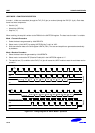
In mode 1, 10-bits are transmitted (through the TxD (P1.5) pin) or received (through the RxD (P1.4) pin). Each data
frame has three components:
— Start bit ("0")
— 8 data bits (LSB first)
— Stop bit ("1")
When receiving, the stop bit is written to the RB8 bit in the UARTCON register. The baud rate for mode 1 is variable.
Mode 1 Transmit Procedure
1. Select the baud rate generated by 16bit BRDATA.
2. Select mode 1 (8-bit UART) by setting UARTCON bits 7 and 6 to '01B'.
3. Write transmission data to the shift register UDATA (F5H). The start and stop bits are generated automatically
by hardware.
Mode 1 Receive Procedure
1. Select the baud rate to be generated by 16-bit BRDATA.
2. Select mode 1 and set the RE (Receive Enable) bit in the UARTCON register to "1".
3. The start bit low ("0") condition at the RxD (P1.4) pin will cause the UART module to start the serial data receive
operation.
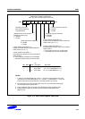
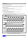
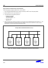
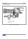
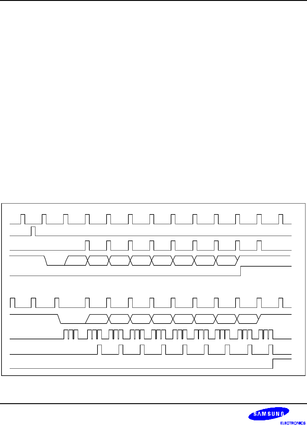
Transmit
TIP
Write to Shift Register (UDATA)
Start Bit
TxD
Stop BitD0 D1 D2 D3 D4 D5 D6 D7
Shift
Tx
Clock
Receive
RIP
Start Bit
Rx
Clock
Stop Bit
RxD
D0 D1 D2 D3 D4 D5 D6 D7
Bit Detect Sample Time
Shift
Figure 13-7. Timing Diagram for UART Mode 1 Operation