


S3C84E5/C84E9/P84E9 INTERRUPT STRUCTURE
5-17
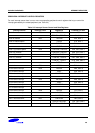
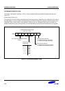
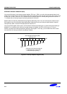
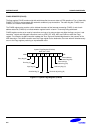
GENERATING INTERRUPT VECTOR ADDRESSES
The interrupt vector area in the ROM (00H–FFH) contains the addresses of interrupt service routines that correspond
to each level in the interrupt structure. Vectored interrupt processing follows this sequence:
1. Push the program counter's low-byte value to the stack.
2. Push the program counter's high-byte value to the stack.
3. Push the FLAG register values to the stack.
4. Fetch the service routine's high-byte address from the vector location.
5. Fetch the service routine's low-byte address from the vector location.
6. Branch to the service routine specified by the concatenated 16-bit vector address.
NOTE
A 16-bit vector address always begins at an even-numbered ROM address within the range of 00H–FFH.
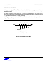
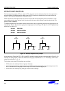
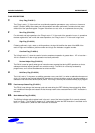
NESTING OF VECTORED INTERRUPTS
It is possible to nest a higher-priority interrupt request while a lower-priority request is being serviced. To do this, you
must follow these steps:
1. Push the current 8-bit interrupt mask register (IMR) value to the stack (PUSH IMR).
2. Load the IMR register with a new mask value that enables only the higher priority interrupt.
3. Execute an EI instruction to enable interrupt processing (a higher priority interrupt will be processed if it occurs).
4. When the lower-priority interrupt service routine ends, restore the IMR to its original value by returning the
previous mask value from the stack (POP IMR).
5. Execute an IRET.
Depending on the application, you may be able to simplify the procedure above to some extent.