Effects Parameters
M7CL Owner’s Manual
261
Appendices
■ DELAY+REV
One input, two output delay and reverb effects in parallel.
■ DELAY→REV
One input, two output delay and reverb effects in series.
■ DIST→DELAY
One input, two output distortion and delay effects in series.
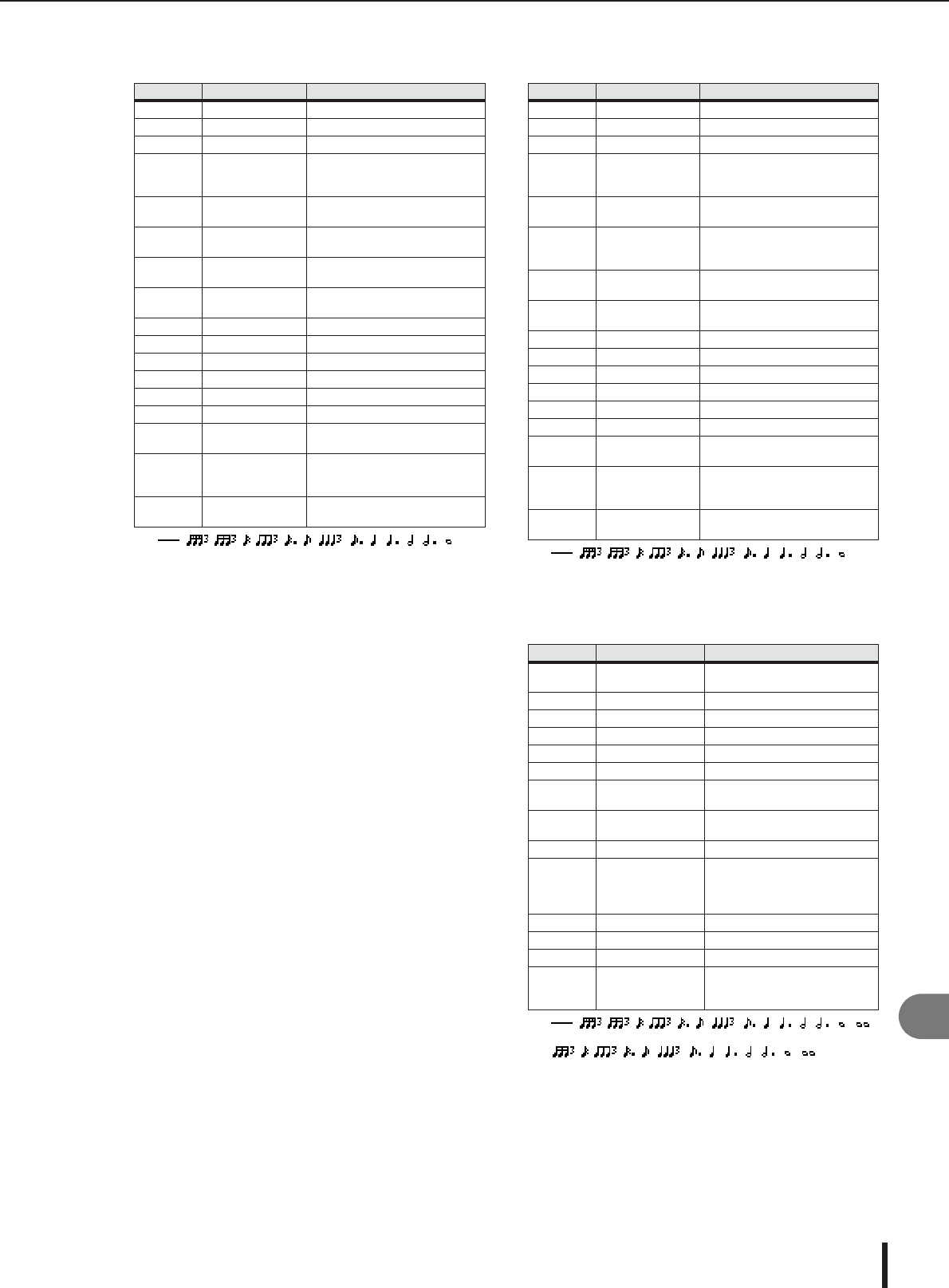
Parameter Range Description
DELAY L 0.0–1000.0 ms Left channel delay time
DELAY R 0.0–1000.0 ms Right channel delay time
FB. DLY 0.0–1000.0 ms Feedback delay time
FB. GAIN –99 to +99%
Feedback gain (plus values for
normal-phase feedback, minus
values for reverse-phase feedback)
DELAY HI 0.1–1.0
Delay high-frequency feedback
ratio
DLY/REV 0–100%
Delay and reverb balance (0% =
all delay, 100% = all reverb)
HPF
THRU, 21.2 Hz–
8.00 kHz
High-pass filter cutoff frequency
LPF
50.0 Hz–16.0 kHz,
THRU
Low-pass filter cutoff frequency
REV TIME 0.3–99.0 s Reverb time
INI. DLY 0.0–500.0 ms Initial delay before reverb begins
REV HI 0.1–1.0 High-frequency reverb time ratio
DIFF. 0–10 Spread
DENSITY 0–100% Reverb density
SYNC OFF/ON Tempo parameter sync on/off
NOTE L
*1
*1.
(Maximum value depends on the tempo setting)
Used in conjunction with TEMPO
to determine left channel DELAY L
NOTE R
*1
Used in conjunction with TEMPO
to determine right channel DELAY
R
NOTE FB
*1
Used in conjunction with TEMPO
to determine FB. DLY
Parameter Range Description
DELAY L 0.0–1000.0 ms Left channel delay time
DELAY R 0.0–1000.0 ms Right channel delay time
FB. DLY 0.0–1000.0 ms Feedback delay time
FB. GAIN –99 to +99%
Feedback gain (plus values for
normal-phase feedback, minus
values for reverse-phase feedback)
DELAY HI 0.1–1.0
Delay high-frequency feedback
ratio
DLY.BAL 0–100%
Delay and delayed reverb balance
(0% = all delayed reverb, 100% =
all delay)
HPF
THRU, 21.2 Hz–
8.00 kHz
High-pass filter cutoff frequency
LPF
50.0 Hz–16.0 kHz,
THRU
Low-pass filter cutoff frequency
REV TIME 0.3–99.0 s Reverb time
INI. DLY 0.0–500.0 ms Initial delay before reverb begins
REV HI 0.1–1.0 High-frequency reverb time ratio
DIFF. 0–10 Spread
DENSITY 0–100% Reverb density
SYNC OFF/ON Tempo parameter sync on/off
NOTE L
*1
*1.
(Maximum value depends on the tempo setting)
Used in conjunction with TEMPO
to determine left channel DELAY L
NOTE R
*1
Used in conjunction with TEMPO
to determine right channel DELAY
R
NOTE FB
*1
Used in conjunction with TEMPO
to determine FB. DLY
Parameter Range Description
DST TYPE
DST1, DST2, OVD1,
OVD2, CRUNCH
Distortion type (DST = distortion,
OVD = overdrive)
DRIVE 0–100 Distortion drive
MASTER 0–100 Master volume
TONE –10 to +10 Tone control
N. GATE 0–20 Noise reduction
SYNC OFF/ON Tempo parameter sync on/off
DLY.NOTE
*1
*1.
(Maximum value depends on the tempo setting)
Used in conjunction with TEMPO
to determine DELAY
MOD.NOT
E
*2
*2.
Used in conjunction with TEMPO
to determine FREQ.
DELAY 0.0–2725.0 ms Delay time
FB. GAIN –99 to +99%
Feedback gain (plus values for
normal-phase feedback, minus
values for reverse-phase feed-
back)
HI. RATIO 0.1–1.0 High-frequency feedback ratio
FREQ. 0.05–40.00 Hz Modulation speed
DEPTH 0–100% Modulation depth
DLY.BAL 0–100%
Distortion and delay balance (0%
= all distortion, 100% = all
delayed distortion)


