


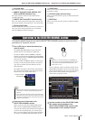
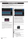
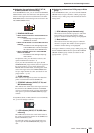
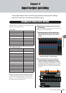
About the OVERVIEW screen
M7CL Owner’s Manual
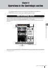
Operations in the Centralogic section
8
99
E
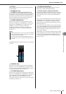
EQ field
This is a graph that shows the approximate EQ response
for each channel.
F
DYNAMICS 1 field
G
DYNAMICS 2 field (input channels only)
For each channel, this shows the name of the type selected
for Dynamics 1, the input level, gain reduction amount,
and threshold. If GATE is selected as the dynamics type, a
three-step indicator shows the presence or absence of a
signal, and the open/closed status of the gate.
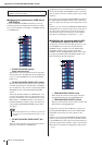
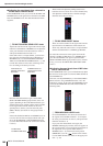
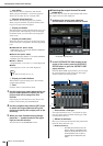
H
TO MIX/TO MATRIX field
This shows the send level of the signal sent from each
channel to the MIX buses / MATRIX buses. (If the send-
destinations are MATRIX buses, an indication of “TO
MATRIX” is shown at the bottom of the field.)
To adjust the send level for each bus, press the corre-
sponding knob to select it, and operate multifunction
encoders 1–8.
If MATRIX channels are selected, the
H
area will change
as follows.
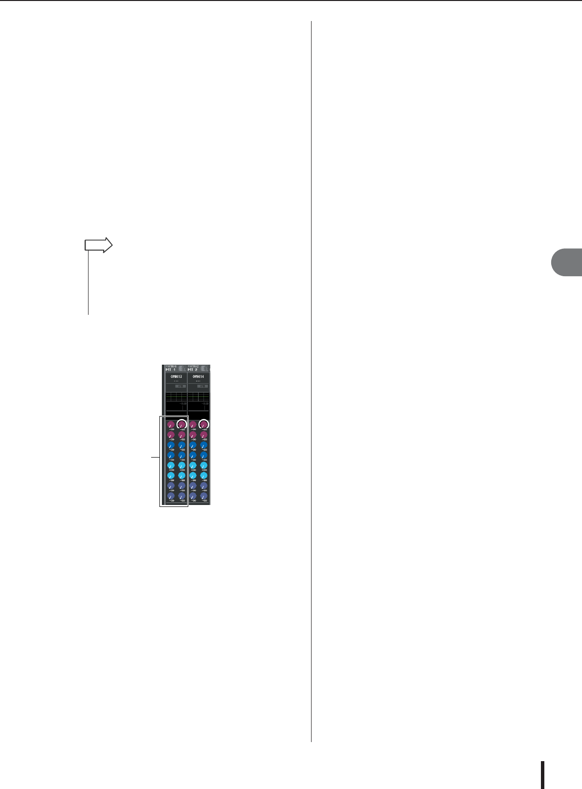
I
FROM MIX field
This shows the send level of the signals sent from MIX
channels 1–16 to each MATRIX bus. To adjust the send
level for each bus, press the corresponding knob to select
it, and operate multifunction encoders 1–8.
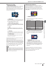
J
TO STEREO/MONO field
This shows the on/off status of the signal sent from each
channel to the STEREO bus and MONO bus, and the pan-
ning of the signal sent to the STEREO bus (or the left/
right volume balance if the send-source is stereo).
To adjust the value, press the knob to select it, and operate
multifunction encoders 1–8.
K
DCA/MUTE GROUP field
This shows the DCA group (input channels only) and
mute group to which each channel belongs.
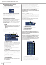
L
Channel number / Channel name field
This shows the number, channel name, and icon for the up
to eight channels that are currently selected for operation
in the Centralogic section (except for the multifunction
encoders).
Area
A
shows the channels that can be controlled by the
OVERVIEW screen, multifunction encoders, [SEL] keys,
and [CUE] keys. Area
L
shows the channels or DCA
groups that can be controlled by the Centralogic section’s
faders and [ON] keys.
For example if you assign DCA groups to the Centralogic
section, the OVERVIEW screen will continue showing the
eight channels that had been displayed until then, and in
this case the channels or DCA groups shown in areas
A
and
L
will be different.
On the M7CL, you can leave the channels/groups assigned
to the Centralogic section fixed, and switch only the eight-
channel groups displayed in the OVERVIEW screen (
→
p. 104), and the content shown in
A
and
L
will differ in
this case as well.
• If input channels are shown, you can use the TO MIX / TO MATRIX
button in the SELECTED CHANNEL VIEW screen to change the
send-destination shown in this field.
•You can also assign the SEND ENCODER MODE function to a
user-defined key, and use it to change the send-destination in the
same way.
HINT
9