


M7CL Owner’s Manual
About the OVERVIEW screen
98
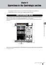
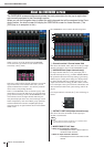
The OVERVIEW screen simultaneously shows the main parameters for the (up to) eight chan-
nels currently assigned to the Centralogic section.
When you use the navigation keys to select the eight channels that will be assigned to the Centr-
alogic section, the touch screen will display the OVERVIEW screen for those channels. (The
[DCA] key is an exception to this.)
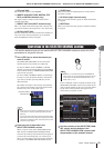
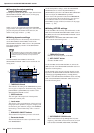
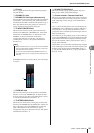
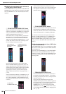
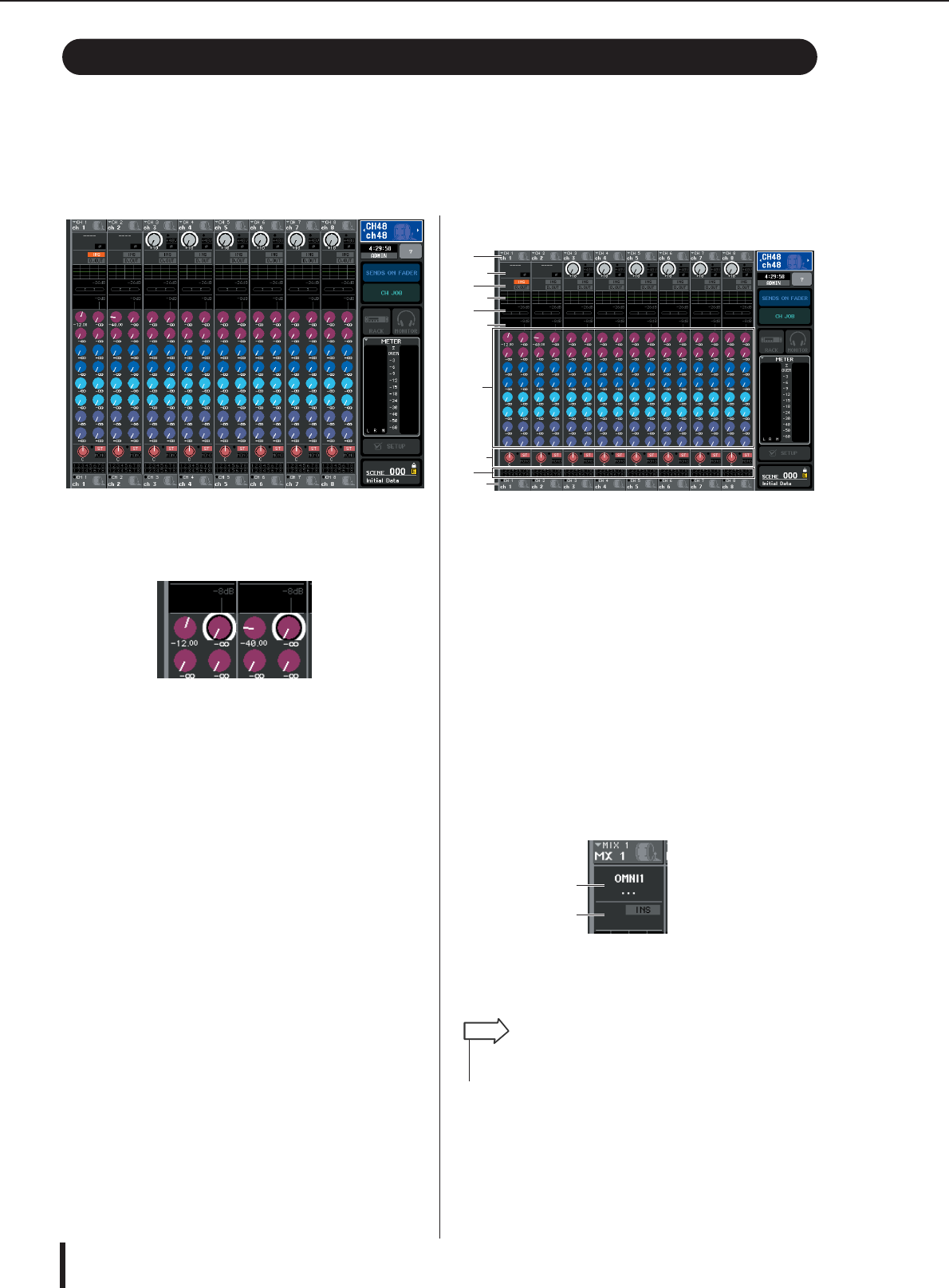
When you press one of the knobs in the OVERVIEW
screen, the same type of knob for each channel will be
enclosed by a heavy frame.
This heavy frame indicates that the parameter correspond-
ing to those knobs can be edited. In this state, you can
operate multifunction encoders 1–8 to edit the parameter
values of the corresponding channels.
There is no OVERVIEW screen for the DCA group. This
means that if you press the [DCA] key to assign the DCA
groups to the Centralogic section, the OVERVIEW screen
will continue to show the eight channels that had previ-
ously been displayed. In this case, the Centralogic section
faders and [ON] keys will control DCA group operations,
and the multifunction encoders and [SEL]/[CUE] keys
will control the up to eight channels shown in the OVER-
VIEW screen.
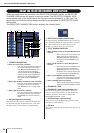
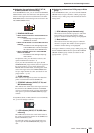
The OVERVIEW screen contains the following items.
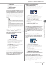
1
Channel number / Channel name field
This shows the number, name, and icon for the up to eight
channels selected for control in the OVERVIEW screen.
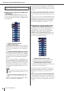
B
HA/PHASE field (input channels only)
For input channels that have a rear panel input jack or
external head amp device (e.g., Yamaha AD8HR, SB168-
ES) patched to them, the head amp settings (gain setting,
phantom power on/off, phase setting) are displayed here.
For input channels that have another input port or rack
output (internal effect or GEQ) patched to them, informa-
tion on the input source (port/rack name and number, card
name and effect module name, phase setting) will be dis-
played.
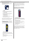
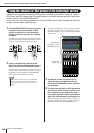
If an output channel is selected, the
B
area will change as
follows.
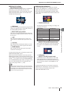
C
OUTPUT PORT field (output channels only)
This shows the name and number of the output port
patched to each channel.
D
INSERT/DIRECT OUT field
• When an input channel is selected
........... This displays the insert or direct output on/
off status of each channel.
• When an output channel is selected
........... This displays the insert on/off status of each
channel.
About the OVERVIEW screen
J
L
1
K
2
4
5
6
7
8
3
4
• If two or more output ports are patched, a “+” symbol is shown
after the name of one of the output ports.
HINT