


FUNCTION REFERENCE 5 - 17
CHANNEL/TRACE SELECTION
Description:
In this family of instruments, the distinction is made between ‘channel’ and ‘trace’.
A channel is referred to as an input channel, complete with AMPL and POS
settings. A trace represents a waveform which has been stored in one of the
register memories. Once such a waveform is recalled from memory, it is displayed
on the screen as a trace.
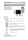
Each channel can be turned ON and OFF by the ON key located near the channel
keys on the front panel. In the digital mode, this key switches the acquisition and
the display on/off.
In the
digital
mode, a waveform which has been previously stored in a register, can
be recalled and displayed via the RECALL menu. One of the registers (M0) is the
acquisition register, where the newly acquired data from the input channels is stored.
The RECALL function only switches on and off the display of the trace and does
not influence the acquisition. It allows the running acquisition to be hidden to give
a better view of the processed results calculated from an acquisition running in
the ‘background’.
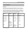
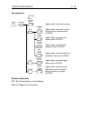
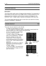
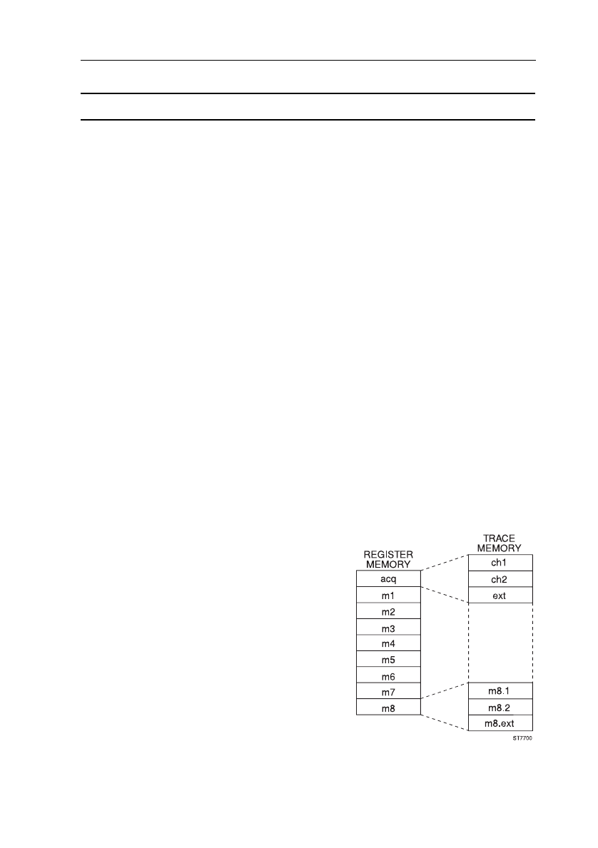
In addition to the acquisition register (M0), the scope provides eight different
register memory locations (50 for the extended memory version). Each memory
location can hold a maximum of one of the following:
4 (3) waveforms of 512 samples.
4 (3) waveforms of 2K samples.
2 (2) waveforms of 4K samples.
1 (1) waveform of 8K samples.
The number of stored waveforms depends on
the selected acquisition length and the number
of channels that were active at the moment of
the acquisition.
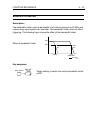
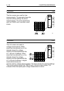
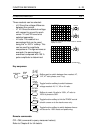
To switch single traces on and off instead of a
total register, the bottom key in the RECALL
menu can be used to select TRACE instead of
REGISTER. The RECALL menu is then trace
oriented instead of register oriented.
Example : m1 changes in m1.1 and m1.2,
representing the labels for the ch1
trace in m1 and the ch2 trace in m1,
respectively. Label m1.e is for the
External Trigger input signal in m1.