


XV
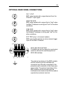
OPTIONAL REAR PANEL CONNECTIONS
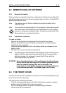
CH1 Y-OUT
BNC output socket with a signal derived from the
Channel 1 input signal.
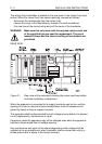
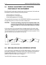
MAIN TB GATE
BNC output socket with a signal that is "high" when
the Main Timebase is running and "low" for the other
conditions.
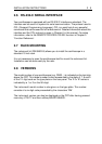
DTB GATE
BNC output socket with a signal that is "high" when
the Delayed Timebase is running and "low" for the
other conditions.
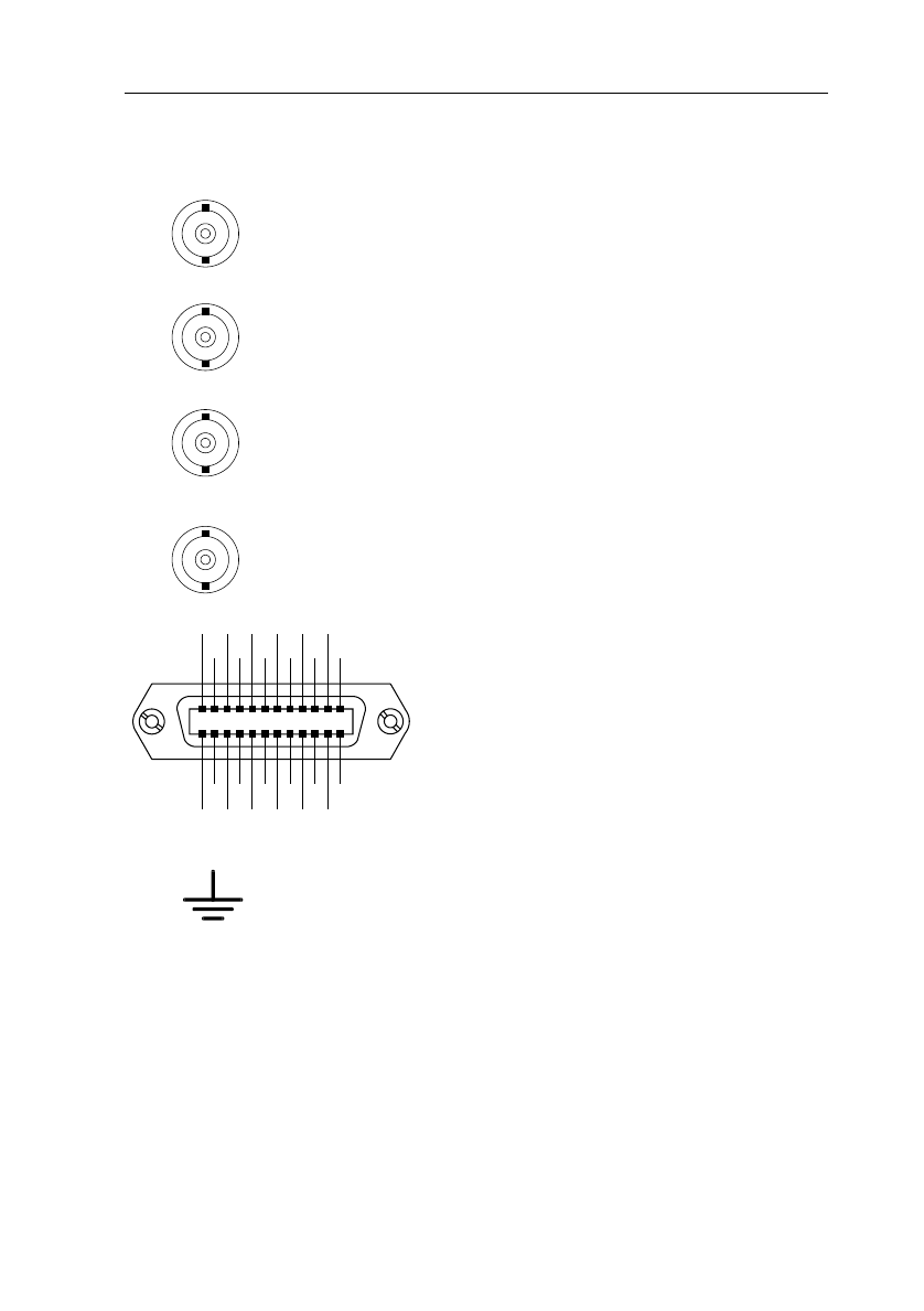
EXT TRIG (only in 4 channel models)
BNC input socket used as an extra external trigger
input for the Main Timebase
IEEE 488.2 BUS OPTION
If installed you will find here the input/output
socket to connect the oscilloscope to an
IEEE 488 interface.
The external conductor of the BNC sockets
and the screening of the interface bus
connectors are internally connected to the
protective earth conductor of the three-core
mains cable. The external conductor of the
BNC sockets and the screening of the
interface bus connectors must not be used as
a protective conductor terminal.
SHIELD
ATN
SRQ
IFC
NDAC
NR
FD
DAV
DIO4
DIO2
EO1
DIO3
DIO1
GND
11
GND
9
GND
7
REN
DIO7
DIO5
LOGIC
GND
GND
10
GND
8
GND
6
DIO8
DIO6
ST6064
12
24
1
13