


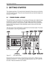

GETTING STARTED 3 - 9
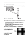
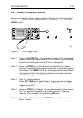
Step 3 You can change the amplitude of the signal in a 1, 2, 5 sequence by
pressing one of the AMPL keys. Note that the bottom of the screen
shows the AMPL/DIV setting of CH1.
Step 4 Press the ON button of CH2 and observe that a second trace is now
visible. The position and amplitude of this channel can be adjusted
similar to the adjustment of CH1. The channel settings are also
displayed in the bottom of the screen.
Press the ON key of CH2 once again to turn this channel off.
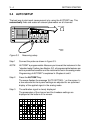
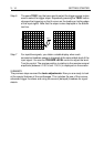
Step 5 Press the AC DC/GND key of CH1 so that a ’⊥’ sign is displayed in the
bottom text line. This interrupts the input signal and connects the input
to the ground. In this case, only the ’base’ line is visible.
Press the AC DC/GND key once again for ac input coupling; the
bottom text line now displays ’~’.
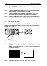
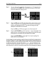
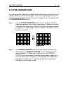
In most cases, dc input coupling is used to show ac as well as dc components of
the signal. However, in some cases where a small ac signal is superimposed on
a large dc voltage, ac input coupling must be used. Then only the ac component
is visible on the screen. The text line shows a ’=’ or ’~’ sign to indicate dc or ac
coupling. Because the calibration signal is a square wave with a low level of 0V
and a high level of +600 mV, the screen shows either of the following two displays:
CH1
100mV
CH1
500mV
ST6681
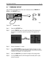
CH1
200mV
CH1
200mV
MTB 200µs
CH1
MTB 200µs
CH1
1
ZERO
LEVEL
1
ZERO
LEVEL
AC INPUT COUPLING
DC INPUT COUPLING
ST6682