


3 - 14 GETTING STARTED
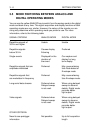
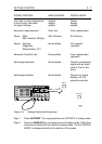
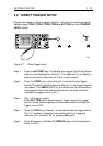
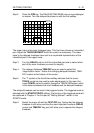
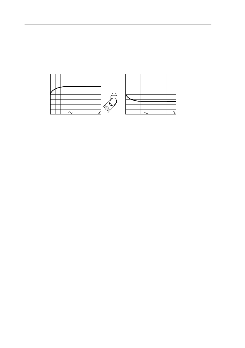
Step 6 The same TRIG1 key that was used to select the trigger source is also
used to select the trigger slope. Repeatedly pressing the TRIG1 button
changes the triggering so that it occurs on the leading or trailing edge
of the input signal. Note that the slope is also displayed in the bottom
text line.
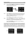
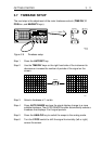
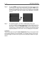
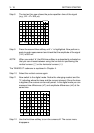
Step 7 For repetitive signals, you obtain a stable display when each
successive timebase sweep is triggered at the same stable level of the
input signal. You use the TRIGGER LEVEL control to adjust the level.
Turn the control. The precise position in relation to the maximum signal
amplitude (between +100 % and -100 %) is displayed on the screen.
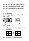
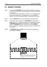
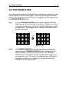
SUMMARY
The previous steps covered the basic adjustments. Now you are ready to look
at the special features of the oscilloscope. This includes the use of the cursors,
advanced trigger functions and using the second (delayed) timebase for signal
details.
CH1
200mV
CH1
200mV
MTB 2µs
CH1
MTB 2µs
CH1
TRIG1
ST6685