HOW TO USE THE INSTRUMENT 4 - 35
TRIGGER LEVEL
- Press the ’level-pp’ softkey to turn it off.
The automatic level detection circuitry is turned off. The trigger level is
no longer clamped within the peak-peak range of the signal. You must
adjust the proper trigger level. While you turn the TRIGGER LEVEL
control, the actual trigger level is displayed in (m)V.
An indicator ’T-’ is displayed next to the channel identifier when the combination
of trigger coupling and channel input coupling is useful (both ac coupled or both
dc coupled).
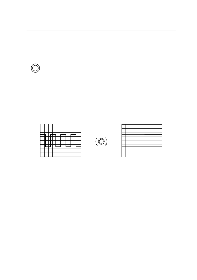
When the ’T-’ is within the signal range, a stable display of the signal is obtained.
When proper triggering takes place, the ARM’D LED is off.
Use the TRIGGER LEVEL control to move the indicator (T-) vertically.
When the trigger level indicator (T-) is outside the signal range, triggering is lost.
Because of the nature of the (Probe Adjust) input signal, it appears that only two
lines are drawn. The timebase is not properly triggered, as is indicated by the
ARM’D LED being turned on.
Note: ’T-’ is an indication for reference only. Its position can differ slightly from
the actual trigger level.
TRIGGER
LEVEL
ST6738
T-
T-
TRIGGER
LEVEL


