


5 - 84 FUNCTION REFERENCE
TRIGGER MAIN TB
Description:
This section deals only with ‘edge’ triggering of the MAIN TB. For TV triggering,
Logic triggering or DEL’D TB triggering, refer to the appropriate sections.
In the
analog
mode triggering determines the start point of the MAIN TB sweep.
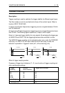
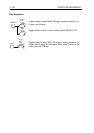
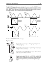
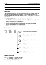
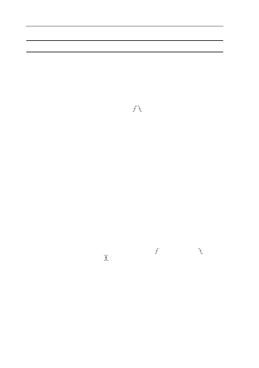
The sweep starts at the moment the signal crosses the trigger level in positive or
negative direction. The slope is selectable ( ), as is shown in the figure below.
In the
digital
mode, the trigger system determines which part of the trace is
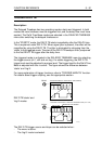
acquired and placed in memory. As in every other Digital Storage Oscilloscope,
signal acquisition through the ADC system is a continuous process, until it is
stopped by the trigger signal. If nothing else would be done, the signal placed in
memory would be the signal prior to the trigger moment and the trigger moment
would be displayed at the end of the screen. For most oscilloscope users this
would be confusing, since most users were taught that the trigger point
determines the beginning of a sweep (as is the case for an analog scope).
Therefore, in actuality, a delay time equivalent to the time of one sweep length is
added, so that it appears as if the trigger moment is displayed at the beginning of
the screen.
The TRIGGER POSITION control allows you to change the time delay between
the trigger point and the digital acquisition. If set to zero, the acquisition is stopped
after a time equivalent to one sweep length has been added so that the trigger
point appears at the beginning of the trace.
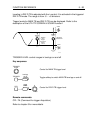
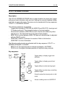
Any of the inputs can be used as the trigger source. The source is selected with
the keys ‘TRIG1, TRIG.. or EXT TRIG’ in the respective control sections. The
same keys are used to toggle between the positive ( ) and negative ( ) slope.
In the digital mode, dual slope ( ) is available. The oscilloscope must be set to
’REAL TIME ONLY’ = yes in the TB MODE menu. Dual slope triggering can be
selected only by the TRIGGER menu key and is restricted to the single shot
modes. The medium level is adjusted by the TRIGGER LEVEL knob. The trigger
gap between positive and negative slope is adjusted by the TRACK knob. For line
frequency related signals, a Line trigger source is available. The Line trigger
source is selected by a softkey under the TRIGGER menu key. The External
Trigger input provides an extra trigger input. This input can be used as the trigger
source for the Main TimeBase (MTB) and Delayed Time Base (DTB). The input
characteristics are simular to the input channels. To reduce the effect on triggering
on noisy signals, trigger filters can be used. For this, lf-rej or hf-rej can be
selected.
Refer to TRIGGER COUPLING and TRIGGER LEVEL for details.