


FUNCTION REFERENCE 5 - 79
TRIGGER COUPLING
Description:
Trigger coupling is used to optimize the trigger stability for different signal types.
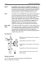
The filter modes ac and dc are identical to those of the vertical inputs. Refer to
function INPUT COUPLING.
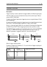
Lf-reject cuts off lower frequencies; triggering occurs on signals between 30 kHz
and full bandwidth.
Hf-reject cuts off higher frequencies; triggering occurs on signal frequencies lower
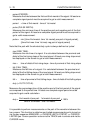
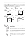
then 30 kHz. The following figure explains ac, lf-reject, and hf-reject.
Noise ’on’ improves trigger stability for noisy signals. By enlarging the trigger gap
(of MAIN TB and DEL’D TB) the triggering becomes less sensitive to noise.
The MAIN TB trigger coupling can be selected in the menu under the TRIGGER
menu key. For DEL’D TB, the menu under the DTB menu key is used; the
selection is possible in ’triggered’ mode (ch1, ch2 and ext trig) only.
Effect of trigger coupling modes
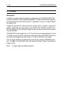
Presence of trigger level indicators (T-, D-) as a function of trigger coupling and
other oscilloscope settings:
−3dB
0dB
10Hz
FULL
BANDWITH
MAT4218
ac-coupled
0dB
−3dB
30kHz
FULL
BANDWITH
lf-reject
FULL
BANDWITH
30kHz
0dB
−3dB
hf-reject
FREQ. FREQ. FREQ.
Trigger Vertical Trigger level indicator
coupling input coupling
ac dc off
dc dc on
lf-rej dc off
hf-rej dc on
all settings ac on
if level-pp is on off