


GETTING STARTED 3 - 13
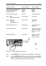
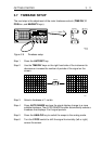
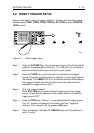
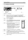
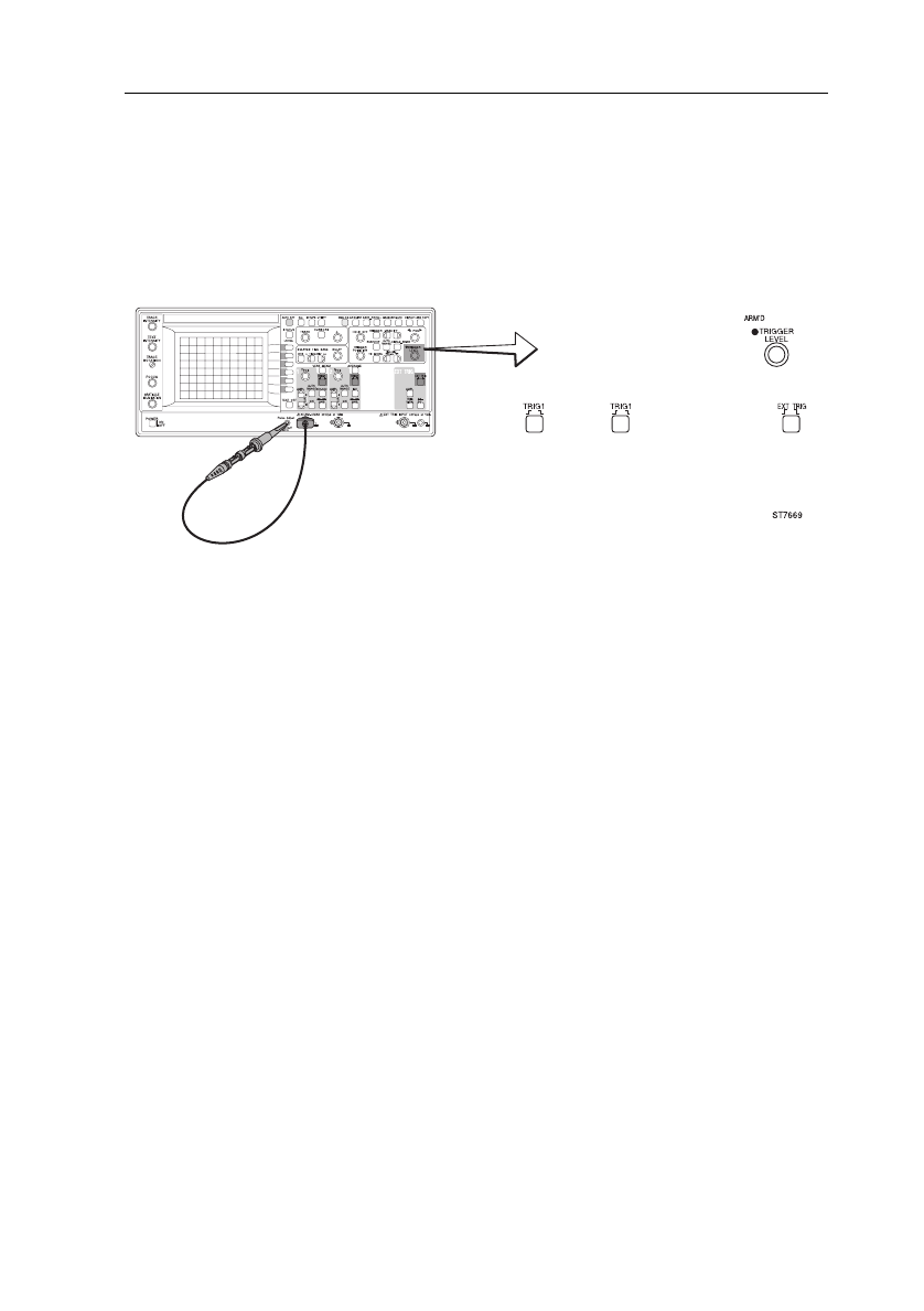
3.9 DIRECT TRIGGER SETUP
Now you are ready to set your trigger conditions. You will use one of the channel
selection keys (
TRIG1, TRIG2, TRIG3, TRIG4 or EXT TRIG
) and the
TRIGGER
LEVEL
control.
Step 1 Press the
AUTOSET
key. The square-wave signal of the Probe Adjust
output is now displayed on channel 1. Turn channel 2 on to display a
second horizontal trace (channel 2 has no input signal).
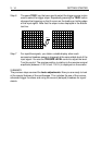
Step 2 Press the
TRIG2
key so that channel 2 is selected as the trigger
source. The result is that the signal on channel 1 is no longer triggered
(not stable). The
ARM’D
LED is on, to indicate that the oscilloscope is
not triggered. Check also that the right side of the bottom text line
indicates the trigger source (’ch2’).
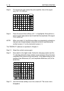
Step 3 Only in 2 channel models
Press
EXT TRIG
key to select External Trigger input as the trigger
source. Check that the rightside of the bottom textline indicates the
trigger source ’EXT’.
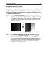
Step 4 Press the
TRIG1
key. Channel 1 is now selected as the trigger source.
The ’ch1’ symbol is displayed in the bottom text line. Triggering
resumes. Turn channel 2 off, by pressing
ON
again.
Step 5 Press the
ns
key of the MainTB
TIME/DIV
keys until the timebase is
set to ’2 µs/div’.
Figure 3.7 Direct trigger setup