


HOW TO USE THE INSTRUMENT 4 - 19
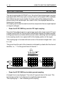
VERTICAL INVERT
The INVERT function in Channel 2 can be used to make it easier to do out-of-
phase signal comparisons. The most common use of the INVERT function is to
obtain the display or make the acquisition of the voltage difference between two
channels. This is done by displaying or capturing the sum of Ch1 and Ch2 as
follows. (This is referred to as the differential mode.)
- Using two probes, connect the Probe Adjust signal to Ch1 and Ch2.
-Press AUTOSET.
- Both Ch1 and Ch2 are now displayed.
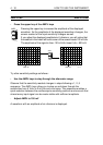
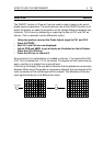
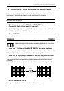
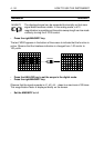
- Adjust POS and AMPL to get a display as illustrated on the left below.
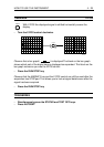
- Press the CH1+CH2 key.
- Press the INV key of channel 2.
Since channel 2 is inverted before it is added to channel 1, the result will be CH1-
CH2. This is indicated as ’1-2’ on the screen. The signals on both inputs are the
same, resulting in a straight line at ground level.
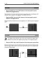
(If the line is not straight, this may be an indication that the probes are not correctly
adjusted. When one of the probes is not properly adjusted, the input signals at the
input connectors of the oscilloscope will be unequal. The difference of the two
input signals shows up in the differential mode).
ST5969
INV
CH1
CH2
200mV
200mV
CHP
MTB
200µs
ch1
1-
2-
CH1
CH2↓
200mV
200mV
CHP
MTB
200µs
ch1
2-
1-
1-2
1+2
CH1+CH2