


Basic Effects Mode
The Structure of Kurzweil Digital Effects (KDFX)
9-15
Each of the FXBuses contains its own signal-processing program, called an FX preset. Each
FX preset has a set of parameters: for example the RT
60
value on a reverb, or the Feedback level
on a delay line. These parameters can be fixed as part of the FX preset, or they can be externally
controlled, from one of two different places. The four FXBuses are also called Insert FX, because
in a conventional studio, that’s where they would be found: in the insert loop of a mixer,
between the channel input and the Mix bus.
There is also a fifth FX preset, which is located on the Auxiliary FX Bus (the Aux bus). The Aux
bus follows the four main FX presets in the signal path, and is normally configured as a global
processor.
Each FX preset consists of an algorithm, modified by user-definable parameters. An algorithm is
a processing function, like a reverb, flanger, or compressor; or a combination of processing
functions in a particular order, like a flanger followed by a delay followed by a reverb. The
algorithms themselves are fixed in ROM, like Kurzweil ROM samples, but you can change the
values of their operating parameters.
Each algorithm requires a certain amount of processing power, which is expressed in
Processing Allocation Units (or PAUs). Simple algorithms require 1 PAU, while more complex
algorithms require up to 4 PAUs. The amount of processing power available in each FX preset is
set by its Allocation parameter. When you are selecting an FX preset for an insert bus, the
number of PAUs its algorithm requires appears on the display, so you can keep track of how
many PAUs are in use.
PAUs are shared among the four insert buses. There is a limit to the total number of PAUs that
the insert buses can use, and that limit is four. PAUs can be manually preassigned to specific
FXBuses, or using “Auto” mode they can be assigned automatically as FX presets are assigned
to the buses. The Aux bus has a separate set of PAUs—three of them—which are not shared with
the insert buses.
Finally, the outputs of the FX presets are passed through to an output routing system—as
specified by the settings on the OUTPUT page in the Studio Editor—where they are sent to the
physical outputs of the K2661.
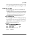
The following equation summarizes studio structure:
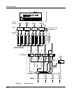
The next page shows a schematic overview of studio structure.
Studio = EQs + Input-page settings + FX presets + Output Editor settings