


Master Mode
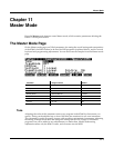
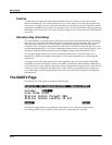
The MAST2 Page
11-7
Editor, Output B is set to FXBus2, thereby sending the signal from the slave program to the B
outputs and from B Right into the right side of the sample input.
The slave program has its output panned hard right within the program, so if you decide to try
using a different slave program, you will probably want to edit the program itself to pan its
output hard right, so you get 100% of the signal. You don't need to worry about setting the
output pair within the program, because the Out parameter on the CH/PRG page of the Setup
Editor is set to KDFX-B in zone 3, thereby overriding any settings from within the program.
The vocoder programs themselves are assigned to KDFX-A, which is being routed to FXBus1.
On the OUTPUT page in the Setup Editor, Output A is set to Mix. So the final output of the
vocoder programs is run through the effect and then comes out the A Outs and the Mix Outs.
Don’t use the Mix audio outputs, however, or you’ll hear the slave program along with the
vocoder.
If you choose to change the effects, you may find it easier to edit the vocoder studio, and try
changing the effects assigned to FXBus1, FXBus2, and AuxFX. But if you want to change to a
different studio, you will need to make sure the following parameters are set correctly: on the
FXBUS page, for FXBus2, set the Level parameters for both Aux and Mix to Off, and on the
OUTPUT page, set Output B to FXBus2.
How Vocoding Works
A vocoder is a device that analyzes the time-varying audio spectrum of one signal (the master)
and imposes that spectrum as a filter on a second signal (the slave.) The method we use is an
emulation of the traditional analog technique involving banks of bandpass filters and envelope
followers.
The master signal is what you send from the microphone, and the slave signal is what you send
from an external synthesizer or other sound source, or a program from the K2661.
The master signal is sent to a number of bandpass filters in parallel. The center frequencies are
spaced to cover the most useful frequencies. The lowest frequency filter is a low pass rather than
a bandpass, which groups all low-frequency components together. Likewise, the highest filter is
a high pass. The outputs of all these bandpass filters go into individual envelope followers,
which detect the level of signal present in each band. The output of the envelope follower is then
used as a control for the slave signal.
The slave signal is also sent to the same number of bandpass filters. These generally have the
same center frequencies as the master bandpasses. The output signals from the slave bandpasses
are multiplied, one by one, by the outputs of the envelope followers (from the master signal).
The resulting products are all added together for the final output.
Since each band requires two layers (one for master and one for slave), the largest number of
bands you can have for vocoding is 24. (24*2=48, which is your maximum polyphony.) The
programs in the Setup called Vocoder-ExtSlave use 24 bands. If you want to use the K2661 to
generate your slave signal, then you have to use either the 22- or 20-band vocoder setups, which
have fewer bands, and therefore leave 4 or 8 voices of polyphony available for the slave signal
program.
Since 48 (or 44 or 40) layers are used, and a drum program has a maximum of 32 layers, we use
two 24 (or 22 or 20) layer programs, on different MIDI channels, that are combined in a setup.
Each of the setups has 3 zones. In the 22- and 20-band vocoder setups, the first two zones are
used for the vocoding programs and the third zone plays the internal program that is used for
the slave signal. In Vocoder-ExtSlave, the third zone is set to transmit via MIDI only, on
Channel 1. (This allows you to play your external sound source, but won't play a K2661 internal
program.)