


79
Basic functions
Saving dataLoading dataProgram
settings
Combination
settings
Producing
songs
Sampling
settings
Creating a
CD
SMF
playback
System
settings
Drum kit
settings
Arpeggiator
settings
Effects
settings
Other
functions
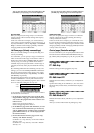
You can also enter these values by holding down the
[ENTER] key and playing a note on the keyboard.
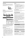
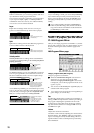
Key Zone Slope
Here you can specify the range of keys over which the
original volume will be reached, starting at the top key
and bottom key.
In the case of the above example, you could set the key
zones so that a portion of timbres 1 and 2 overlaps (i.e., is
layered) with timbre 3, and set “Top Slope” and “Bottom
Slope” so that the sound changes gradually, instead of
changing suddenly between B3 and C4.
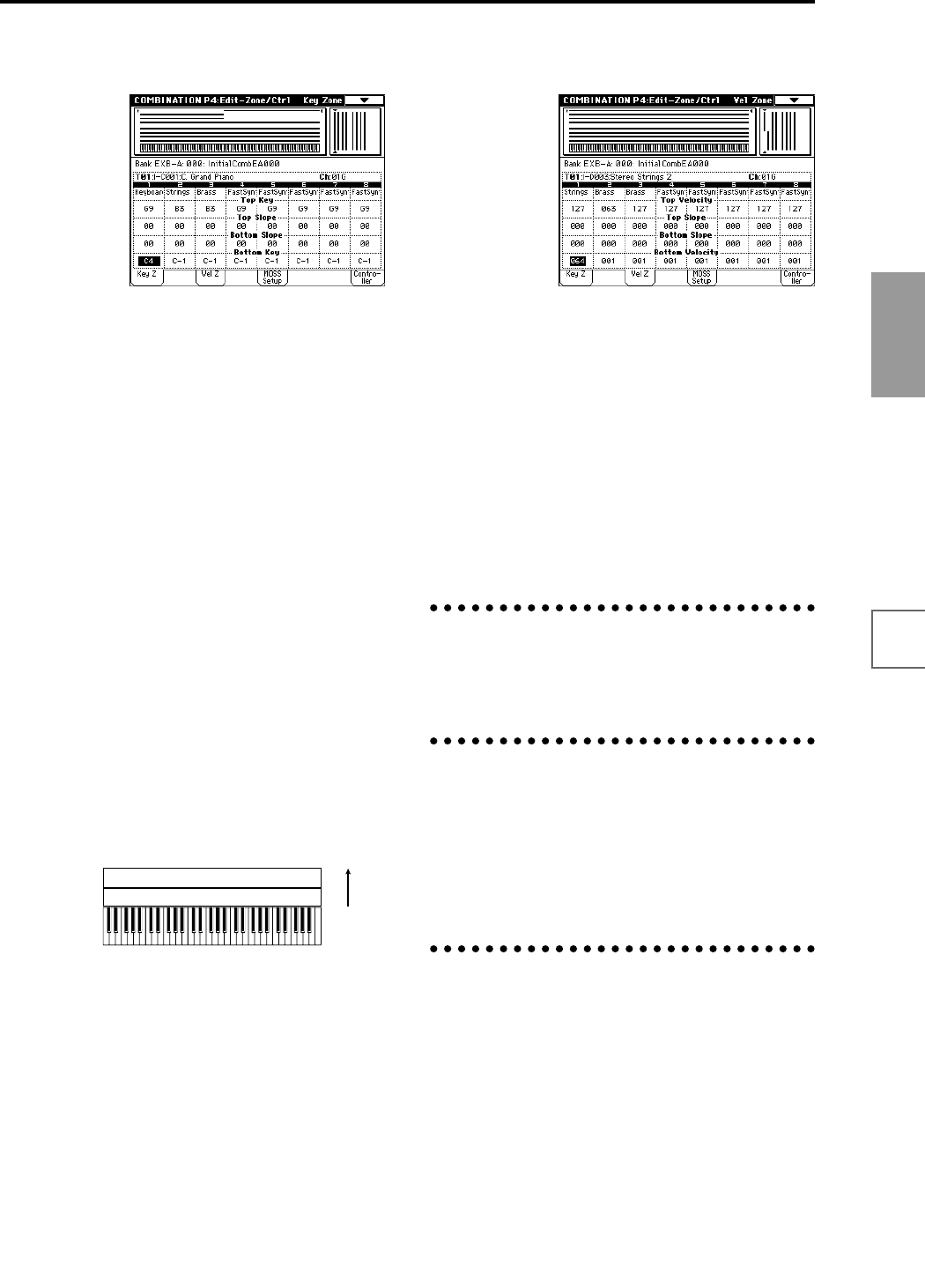
Vel Zone page (Velocity zone settings)
Here you can make settings for velocity switching and
velocity crossfading.
For each timbre, you can specify a range of velocities for
which it will sound. The range of velocities for which a
timbre will sound is called a Velocity Zone. By setting a
velocity zone, you can set up a timbre which will be
sounded only by notes played within a certain range of
velocities, and not by notes played outside this Velocity
Zone.
By combining timbres that have differing velocity zone
settings, you can create velocity switched combinations.
The upper and lower limits of the velocity zone of each
timbre are determined by the “Top Velocity” and “Bot-
tom Velocity” respectively.
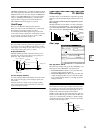
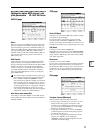
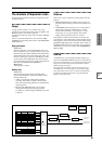
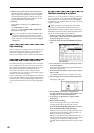
The following diagram shows an example of a velocity
switched combination in velocity will switch between
timbres 1 and 2 to play different programs. Such combina-
tions are created by setting the velocity zone.
As an example, we will explain how to create a combina-
tion like the one shown above.
1 In the P0: Play, Program Select page or the P1: Edit-
Program/Mixer, Prog page, use the “Program Select”
area to select the program that will be used for each
timbre 1 and 2.
Select a brass program for timbre 1.
Select a strings program for timbre 2.
2 In the MIDI Ch page of P2: Edit-Trk Param, set “Sta-
tus” to INT for all the timbres that you wish to use,
and set “MIDI Channel” to either Gch or to match the
global MIDI channel (a “G” will be displayed after
the channel number).
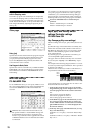
3 In P4: Edit-Zone/Ctrl Vel Zone page, set the “Top
Velocity” and “Bottom Velocity.”
Set timbre 1 to a “Top Velocity” of 127 and a “Bottom
Velocity” of 64.
Set timbre 2 to a “Top Velocity” of 63 and a “Bottom
Velocity” of 1.
You can also enter these values by holding down the
[ENTER] key and playing a note on the keyboard.
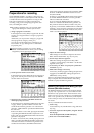
Velocity Zone Slope
Here you can specify the range of values over which the
original volume will be reached, starting from the top
velocity and bottom velocity.
In the case of the above example, you could set the veloc-
ity zones of the two timbres so that they partially overlap,
and set “Top Slope” and “Bottom Slope” so that the sound
changes gradually, instead of changing suddenly between
velocity values of 63 and 64.
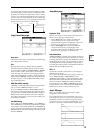
Control page (Controller settings)
For each combination, you can specify the functions of the
B-mode functions of REALTIME CONTROLS knobs [1]–
[4], and the [SW1] and [SW2.] (☞p.145, PG p.43, 249, 250)
Arpeggiator settings
P7: Edit-Arp.
Indicates settings for the arpeggiator (☞p.132).
Insert Effect settings
P8: Edit-Insert FX
Indicates the insert effects, and allows you to adjust their
settings.
Specifies the routing for each timbre (i.e., how it is sent to
the insert effect, master effects, and individual outputs).
(☞p.141)
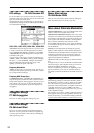
Master Effect settings
P9: Edit-Master FX
Indicates the naster effects, and allows you to adjust their
settings.
Here you can also make master EQ settings (☞p.142).
Strings
Velocity
switch
Timbre 1
Timbre 2
Brass
127
64
63
1