


12 Analog I/O & Digital I/O
01V96i—Reference Manual
Analog I/O &
Digital I/O
This chapter describes the 01V96i’s analog and digital
input/output connectors as well as the basic operations
involving the digital I/Os.
Analog Inputs & Outputs
Input Section
The 01V96i’s top panel features input connectors, which
enable you to connect microphone and line-level sources.
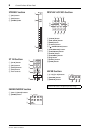
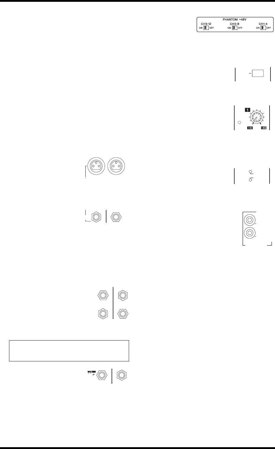
• INPUT connectors A 1–12
These balanced TRS-type
phone connectors accept
line-level and microphone sig-
nals. The nominal input range is
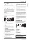
–60 dB through +4 dB. The phantom [+48V] switches on
the rear panel turn on or off the +48V phantom power
feed to these inputs.
• INPUT connectors B 1–12
These balanced TRS-type con-
nectors accept line-level and
microphone signals. The nominal input range is –60 dB
through +4 dB.
You cannot use same-numbered INPUT A and INPUT B
connectors simultaneously. (For example, you cannot use
INPUT A-2 and INPUT B-2 at the same time.) If you
connect cables to A and B connectors of the same num-
ber, only the signal from INPUT B is effective (e.g., B-2
takes priority over A-2).
•INPUT connectors 13–16
These balanced TRS-type phone con-
nectors accept line-level signals. When
the AD 15/16 source selector is turned
on (pushed in), signals from INPUT 15
and 16 are ignored. Instead, signals from
the 2TR IN connector will be routed to AD Input Chan-
nels 15 and 16.
• INSERT I/O connectors
These TRS-type phone connectors
are used to insert external devices,
such as effects processors, into AD Input Channels.
•Phantom Power
Inputs 1 through
12 feature switch-
able +48V phantom powering for use with con-
denser-type microphones and direct boxes. The phantom
[+48V] switches on the rear panel turn on or off the +48V
phantom power feed to the corresponding inputs.
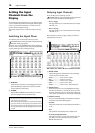
•PAD switches
Inputs 1 through 12 feature pad
switches, which attenuate input
signals by 20 dB. These switches
are effective on both INPUT A and B signals.
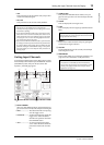
•GAIN controls
Inputs 1 through 16 feature
rotary gain controls that adjust
input sensitivity. Input sensitivity
for INPUT connectors 1–12
ranges from –16 dB to –60 dB when the Pad is off, and
from +4 dB to –40 dB when the Pad is on. Input sensitiv-
ity for INPUT connectors 13–16 ranges from +4 dB to
–26 dB.
•PEAK & SIGNAL Indicators
The SIGNAL indicator lights up
when the input signal level at
INPUTs 1–16 exceeds –34 dB.
The PEAK indicator lights up when the input signal level
is 3 dB below clipping.
•2TR IN connectors
These unbalanced RCA phono connec-
tors accept line-level signals from
devices such as CD players.
When the AD 15/16 source selector is
turned on (pushed in), signals input at
these conductors are routed to AD
Inputs 15 and 16. When the Monitor source selector is
turned on (pushed in), you can monitor these signals
from the MONITOR OUT connectors.
Tip: You can patch signals input from the INPUT connectors
to any Input Channels. (See page 43 for information on
patching input signals to Input Channels.)
AA
21
BB
INPUT
(BAL)
16
1513
14
INSERT I
/
O INSERT I
/
O
INSERT
OUTIN
(UNBAL)
20dB
PAD
20dB
GAIN
-16
-60
PEAK
SIGNAL
GAIN
L
R
IN OUT
2TR
-10dBV
(UNBAL)