


174 Appendix: MIDI
01V96i—Reference Manual
If [TABLE] is selected
If [NRPN] is selected
*1) The second and subsequent STATUS need not be added during
transmission. Reception must be implemented so that reception oc-
curs whether or not STATUS is present.
2.4 PROGRAM CHANGE (Cn)
Reception
If [Program Change ECHO] is ON, these messages are echoed from MIDI
OUT.
If [Program Change RX] is ON and the [Rx CH] matches, these messages will
be received. However if [OMNI] is ON, they will be received regardless of the
channel. When a message is received, a Scene Memory will be recalled accord-
ing to the settings of the [Program Change Table].
Transmission
If [Program Change TX] is ON, this message is transmitted according to the set-
tings of the [Program Change Table] on the [Tx CH] channel when a scene
memory is recalled.
If the recalled scene has been assigned to more than one program number, the
lowest-numbered program number will be transmitted. Transmission to Studio
Manager using Program Change messages will not be performed since there is
no guarantee that the contents of the tables will match. (Parameter Changes will
always be used.)
2.5 TIMING CLOCK (F8)
Reception
It is used to control effects. This message is transmitted 24 times per quarter
note.
2.6 ACTIVE SENSING (FE)
Reception
Once this message has been received, the failure to receive any message for an
interval of 400 ms or longer will cause MIDI transmission to be initialized, such
as by clearing the Running Status.
2.7 SYSTEM RESET (FF)
Reception
When this message is received, MIDI communications will be cleared, e.g., by
clearing the Running Status.
2.8 SYSTEM EXCLUSIVE MESSAGE (F0)
2.8.1 MIDI MACHINE CONTROL (MMC)
These messages are transmitted when the Machine Control section of the
01V96i is operated. For details, refer to the MMC specification.
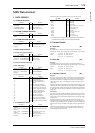
2.8.2 BULK DUMP
This message sends or receives the contents of various memories stored within
the 01V96i.
The basic format is as follows.
For DUMP DATA
F0 43 0n 7E cc cc <Model ID> tt mm mm [Data …] cs F7
For DUMP REQUEST
F0 43 2n 7E <Model ID> tt mm mm F7
A unique header (Model ID) is used to determine whether the device is a
01V96i.
CHECK SUM is obtained by adding the bytes that follow BYTE COUNT
(LOW) and end before CHECK SUM, taking the binary compliment of this
sum, and then setting bit 7 to 0.
CHECK SUM = (-sum)&0x7F
Reception
This message is received if [Bulk RX] is ON and the [Rx CH] matches the device
number included in the SUB STATUS.
When a bulk dump is received, it is immediately written into the specified
memory.
When a bulk dump request is received, a bulk dump is immediately transmit-
ted.
Transmission
This message is transmitted on the [Tx CH] by key operations in the
[MIDI]-[BULK DUMP] screen.
A bulk dump is transmitted on the [Rx CH] in response to a bulk dump request.
The data area is handled by converting seven words of 8-bit data into eight
words of 7-bit data.
Conversion from actual data into bulk data
d[0~6]: actual data
b[0~7]: bulk data
b[0] = 0;
for( I=0; I<7; I++){
if( d[I]&0x80){
b[0] |= 1<<(6-I);
}
b[I+1] = d[I]&0x7F;
}
Restoration from bulk data into actual data
d[0~6]: actual data
b[0~7]: bulk data
for( I=0; I<7; I++){
b[0] <<= 1;
d[I] = b[I+1]+(0x80&b[0]);
}
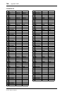
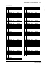
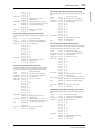
2.8.2.1 Scene memory bulk dump format (compress)
The 01V96i can transmit and receive scene memories in compressed form.
STATUS 1011nnnn Bn
Control change
DATA 0nnnnnnn nn
Control number (0-95, 102-119)
0vvvvvvv vv
Control Value (0-127)
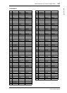
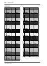
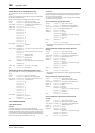
STATUS 1011nnnn Bn
Control change
DATA 01100010 62
NRPN LSB
0vvvvvvv vv
LSB of parameter number
STATUS 1011nnnn Bn
Control change *1
DATA 01100011 63
NRPN MSB
0vvvvvvv vv
MSB of parameter number
STATUS 1011nnnn Bn
Control change *1
DATA 00000110 06
MSB of data entry
0vvvvvvv vv
MSB of parameter data
STATUS 1011nnnn Bn
Control change *1
DATA 00100110 26
LSB of data entry
0vvvvvvv vv
LSB of parameter data
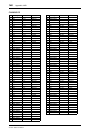
STATUS 1100nnnn Cn
Program change
DATA 0nnnnnnn nn
Program number (0-127)
STATUS 11111000 F8
Timing clock
STATUS 11111110 FE
Active sensing
STATUS 11111111 FF
System reset
n
Device Number
cc cc
DATA COUNT (the number of bytes that
follow this, ending before the checksum)
4C 4D 20 20 38 43 39 33
Model ID
tt
DATA TYPE
mm mm
DATA NUMBER
cs
CHECK SUM
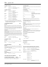
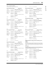
STATUS 11110000 F0
System exclusive message
ID No. 01000011 43
Manufacture’s ID number (YAMAHA)
SUB STATUS 0000nnnn 0n
n=0-15 (Device number=MIDI Channel)
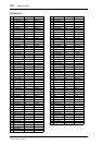
FORMAT No. 01111110 7E
Universal bulk dump
COUNT HIGH 0ccccccc ch
data count = ch * 128 + cl
COUNT LOW 0ccccccc cl
01001100 4C
‘L’
01001101 4D
‘M’
00100000 20
‘ ’
00100000 20
‘ ’
00111000 38
‘8’
01000011 43
‘C’
00111001 39
‘9’
00110011 33
‘3’
DATA NAME 01101101 6D
‘m’
0mmmmmmm mh
m=0-99, 256, 8192(Scene0-99, EDIT
BUFFER, UNDO)