17
Front and Rear Panel
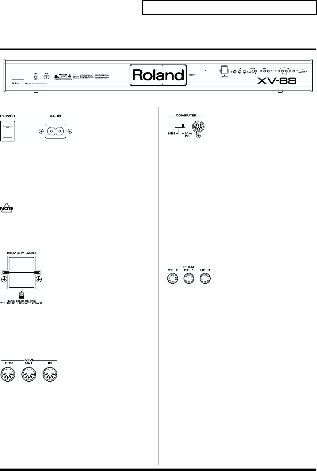
Rear Panel
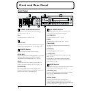
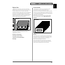
fig.00-05
fig.00-06
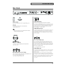
Power Switch
Press to turn the power on/off. → (Quick Start; p. 18)
AC Inlet
Connect the included power cord to this inlet.
→ (Quick Start; p. 16)
With units rated for 117V operation, the AC cable is
already connected to the unit.
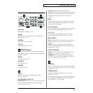
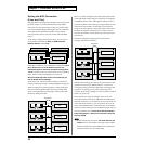
fig.00-07
MEMORY CARD Slot
A memory card (SmartMedia) can be inserted here.
→ (p. 167, p. 179)
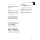
fig.00-08
MIDI Connectors (IN, OUT, THRU)
These connectors can be connected to other MIDI devices to
receive and transmit MIDI messages.
→ (p. 203, p. 269, Quick Start; p. 16)
fig.00-09
COMPUTER Switch
Sets this switch depending on the type of computer
connected to COMPUTER connector, or the software you are
using. Turn the power off before changing the setting of this
switch. If you wish to use the MIDI connectors, set this
switch to MIDI. → (p. 208, p. 209)
COMPUTER Connector
A special Computer cable can be connected here. The type of
cable required will depend on your computer. When the
COMPUTER switch is set to MIDI, this connector cannot be
used. → (p. 209)
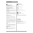
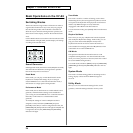
fig.00-10
CTL 1, CTL 2 PEDAL Jack
You can connect optional expression pedals (EV-5, etc.) to
these jacks. By assigning a desired function to a pedal, you
can use it to select or modify sound or perform various other
control. You can also connect optional pedal switches (DP-2,
DP-6, etc.) to sustain sound.
→ (p. 172, Quick Start; p. 16, p. 69)
HOLD PEDAL Jack
An optional pedal switch (DP-2, DP-6, etc.) can be connected
to this jack for use as a hold pedal. → (p. 43, p. 172, Quick
Start; p. 16, 69)
This can also be set so it supports the use of half-pedaling
techniques. So, after connecting an optional expression pedal
(EV-5, etc.), you can employ pedal work to achieve even finer
control in performances in which piano tones are used.
→ (p. 172)


