


109
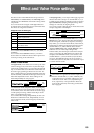
Valve Force settings
Valve Force is an analog circuit that uses a 12AU7 (ECC82)
vacuum tube. It uses a single vacuum tube to deliver ste-
reo-in/stereo-out operation.
By generating the rich overtones and smooth distortion
that are typical of vacuum tubes, Valve Force produces
natural depth and a fat, driven tone. Valve Force also
includes a low-frequency enhancing “ultra boost” circuit.
You can apply Valve Force to the final stage of a program,
combination, song, or sample playback to add rich over-
tones and smooth distortion, or use insert effects and mas-
ter effects (except for sample playback) in conjunction
with Valve Force to create your sound.
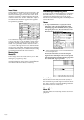
Valve Force settings for a program
1 Press the Valve Force [ON/OFF] key to turn Valve
Force on. (The key will light.)
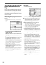
Placement
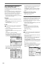
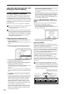
2 Access the Program P9: Edit-Master Effect, VALVE
page.
3 Use “Placement” to specify where you want to place
the Valve Force circuit.
If you set “Placement” to Final, the Valve Force circuit
will be placed after conversion to an analog signal by
the Main Output L/R output DAC (Digital Analog
Converter). After passing through Valve Force, the sig-
nal will be output to AUDIO OUTPUT L/MONO, R
and from the headphone jack.
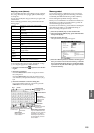
If you set “Placement” to Insert (User 3/4 BUS), Valve
Force will be placed after conversion to an analog sig-
nal by the Indiv. Output 3/4 output DAC (Digital Ana-
log Converter). Bus 3/4 will be the input to Valve
Force, and will simultaneously be output from Individ-
ual 3/4.
After passing through Valve Force, the signal will be
converted back into digital form by the ADC (Analog
Digital Converter), and sent to the insert effects, master
effects, L/R, Individual 1/2, and 3/4 buses as specified
by the “Pan (CC#8)” “BUS Select,” “Send1,” and
“Send2” settings.
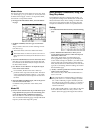
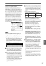
In/Out
You can’t use Valve Force on the L/R output from S/
P DIF, nor when resampling the L/R output in the
various modes.
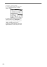
4 Specify the input/output destination for Valve Force.
If “Placement” = Final:
Valve Force will be inserted as the final stage of the L/
R output.
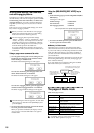
If “Placement” = Insert (Use 3/4 BUS):
If you want to send the output of oscillator 1,2 to Valve
Force, set “BUS Select (IFX/Indiv.Out Assign)” to 3/
4(Tube), 3(Tube), or 4(Tube).
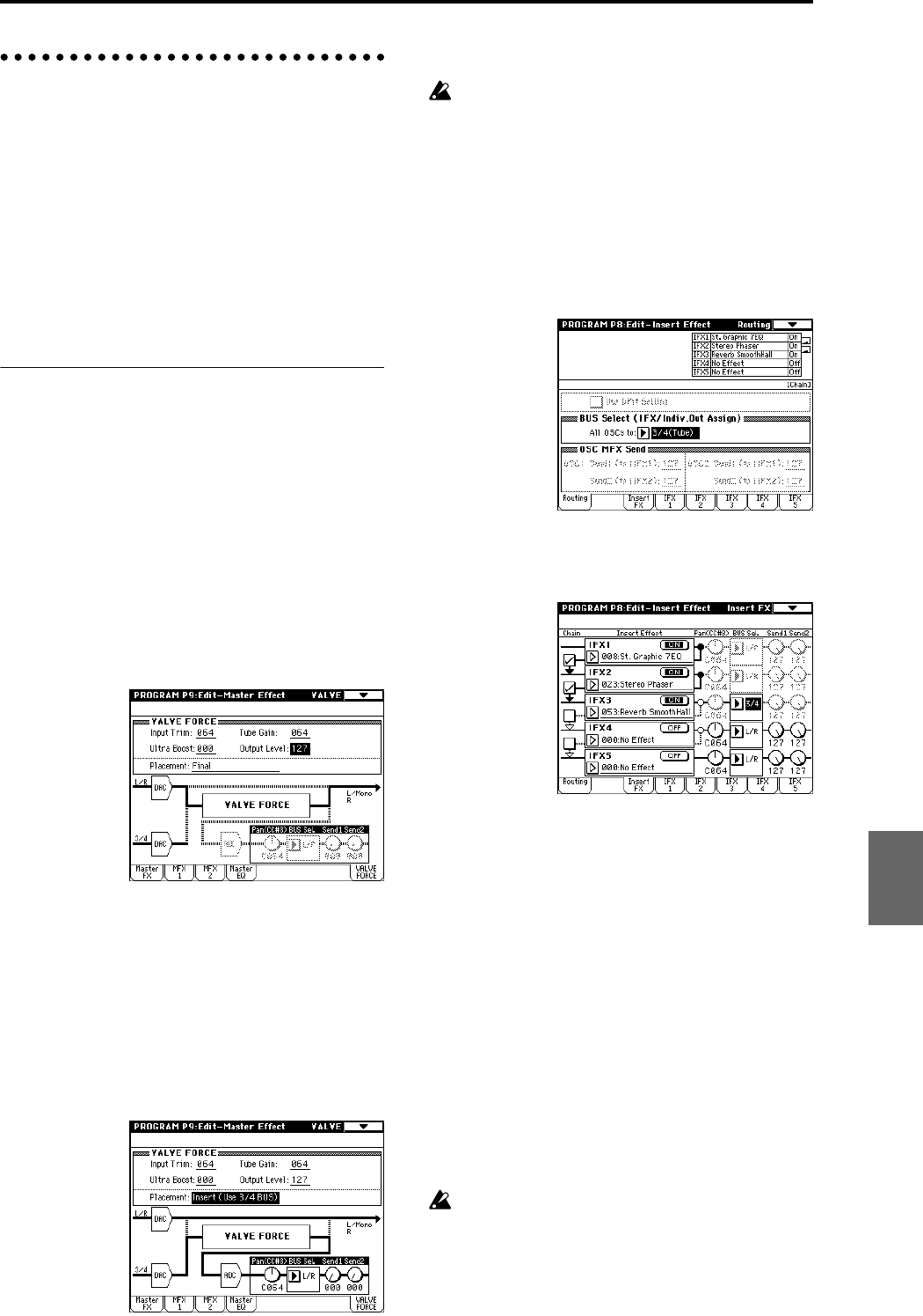
If you want to send the signal through an insert effect
and then into Valve Force, set “BUS Select (IFX/
Indiv.Out Assign)” to the insert effect, and set the
post-IFX “BUS Sel.” to 3/4(Tube), 3(Tube), or 4(Tube).
The output from Valve Force is assigned by the Pro-
gram P9: Edit-Master Effect, VALVE page “BUS Sel.”,
“Send1,” and “Send2” settings.
Use “BUS Sel.” to send the signal to the L/R bus,
insert effect IFX1–5 bus, or 1, 2 bus. “Send1” and
“Send2” adjust the send levels to the master effects.
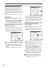
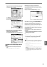
Adjusting the Valve Force settings
5 Adjust the Valve Force settings.
Select VALVE FORCE as the control function for the
front panel REALTIME CONTROLS knobs, or use the
Program P9: Edit-Master Effect, VALVE page to adjust
the settings.
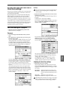
Depending on the sound you are using, you may hear
noise if you turn the Valve Force knobs or edit Valve
Force parameters while sound is being produced.
Input Trim: adjusts the input level to Valve Force
Ultra Boost: adjusts the mix level to the ultra-boost
circuit located at the beginning of Valve
Force
Tube Gain: adjusts the vacuum tube gain
Output Level: adjusts the output level of Valve Force
Program
Combination
SequencerSamplingSong PlayGlobalEffectMedia, etcPresetOther