Volume and status of the Style parts
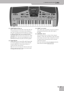
E-80 Music Workstation
r
107
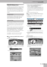
As you know (see p. 33), the UP1, LW1 and MBS parts
can be used as virtual organ parts, in which case they
control a separate sound engine that is based on
Roland’s Virtual ToneWheel modeling technology. To
simulate the behavior of a “real” organ, the level of
the HARMONIC BAR parts cannot be set individually.
You need to use the sliders below the display for that
(to set the volume of each individual footage).
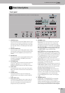
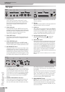
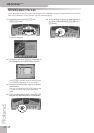
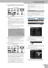
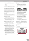
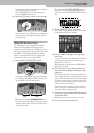
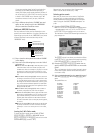
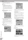
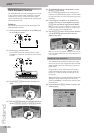
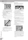
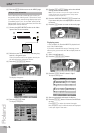
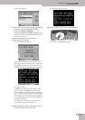
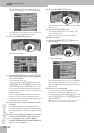
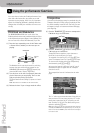
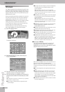
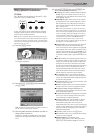
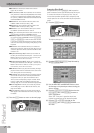
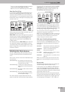
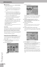
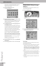
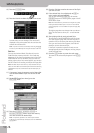
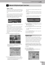
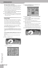
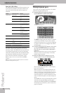
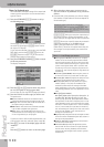
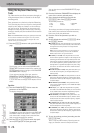
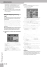
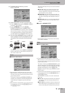
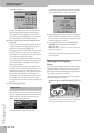
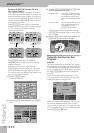
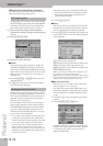
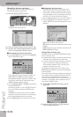
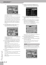
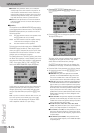
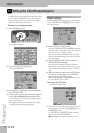
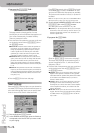
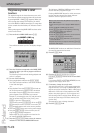
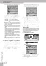
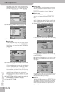
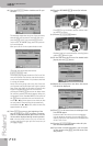
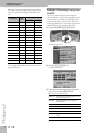
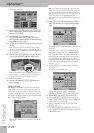
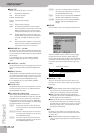
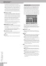
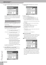
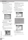
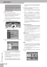
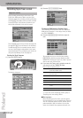
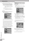
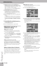
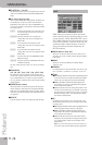
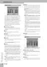
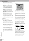
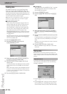
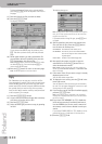
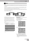
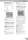
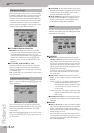
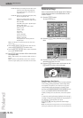
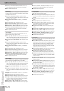
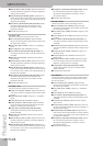
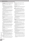
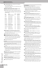
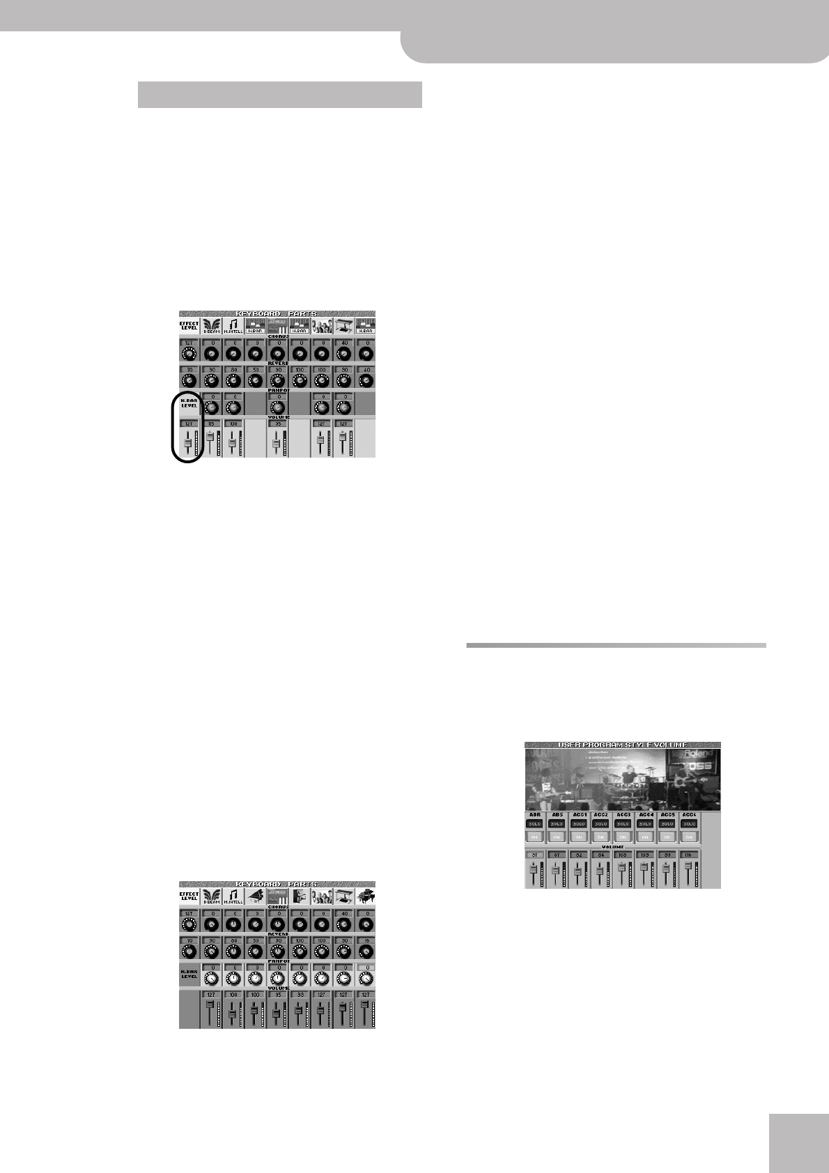
If at least one of the eligible Keyboard parts controls
the HARMONIC BAR sound engine, the mixer looks as
follows:
The fader and pan knob icons of the Keyboard part(s)
assigned to the HARMONIC BAR sound engine disap-
pear, while a new fader icon appears in the leftmost
“module”. (In this example all three parts, UP1, LW1
and MBS, are used as HARMONIC BAR parts.)
Use the [EFFECT] slider below the display to change
the volume of the HARMONIC BAR section (i.e. all
three eligible parts).
Note: The stereo position (PANPOT) of the HARMONIC BAR
parts cannot be changed.
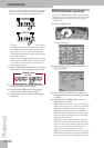
(4) After setting the levels, you can use the [BALANCE]
knob to establish the correct balance between the
Keyboard parts and the Recorder/Arranger.
“Mixing”, as you may know, entails a lot more than
just getting the balances right. It also involves speci-
fying the stereo placement of sounds and the
amount of effect that should be applied. So here we
go…
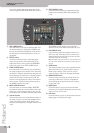
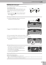
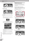
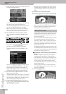
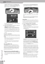
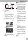
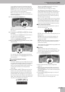
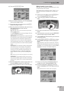
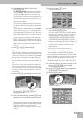
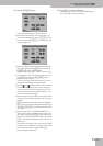
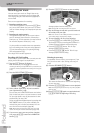
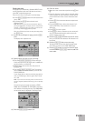
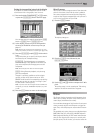
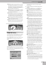
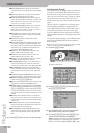
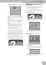
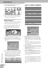
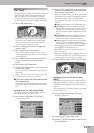
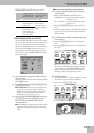
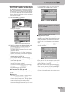
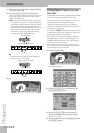
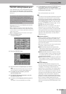
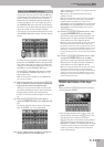
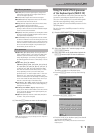
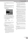
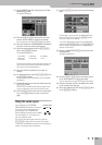
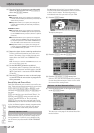
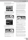
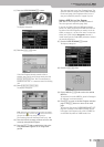
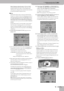
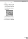
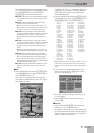
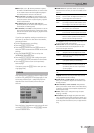
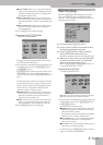
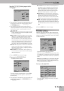
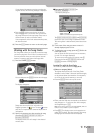
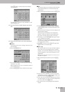
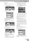
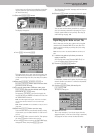
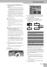
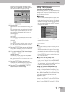
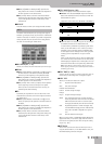
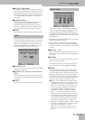
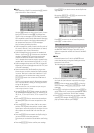
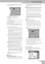
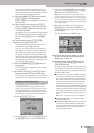
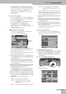
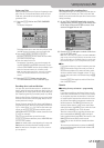
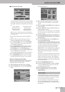
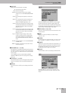
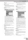
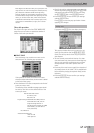
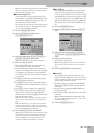
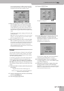
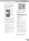
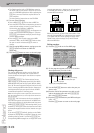
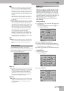
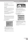
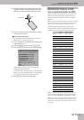
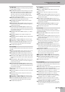
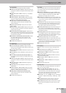
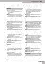
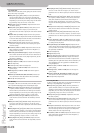
(5) Press the [PANPOT/VOLUME] button again to
assign the PANPOT function to the assignable slid-
ers.
The display page still looks as shown in (2), except
that the “PANPOT” row is now emphasized:
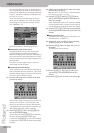
(6) Use the 9 sliders below the display to change the
stereo placement of the available parts.
“L63” corresponds to hard left, “0” to dead center and
“R63” to hard right.
Note: The left-most slider (EFFECT) does nothing while
“PANPOT” is selected.
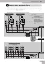
Note: The assignable slider functions can also be selected by
pressing any control in the desired display row (VOLUME,
PANPOT, REVERB or CHORUS). You can then use the
[DATA÷ENTRY] dial and the [DEC]/[INC] buttons to directly edit
the parameter of the assigned part. (You can even press the
[DATA÷ENTRY] dial and enter the desired value via the on-
screen numeric pad.)
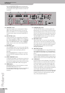
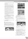
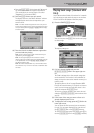
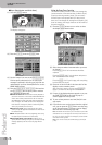
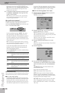
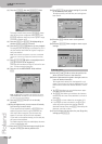
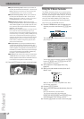
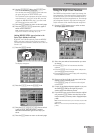
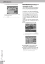
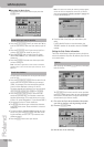
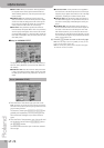
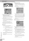
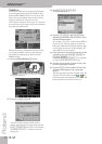
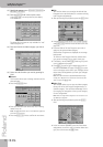
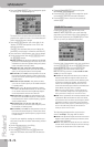
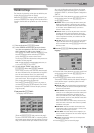
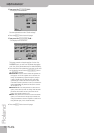
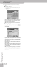
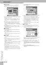
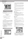
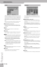
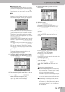
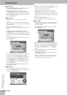
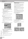
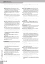
(7) Press the [CHORUS÷REVERB] button once or twice
to assign the REVERB function to the sliders.
Specify how much reverb should be applied to the
Keyboard parts. The effects parameters themselves
can be edited on an Effect page (see below).
Note: At this stage, the EFFECT slider (far left) can be used to
set the output level of the Reverb processor. Setting this
parameter to “0” means that you no longer hear the effect in
question. By contrast, setting the REVERB parameter of a Key-
board part to “0” means that only the part in question is no
longer processed by the effect, while the remaining Keyboard
parts are.
(8) Press the [CHORUS÷REVERB] button once or twice
to assign the CHORUS function to the sliders.
Specify how much chorus should be applied to the
Keyboard parts. The effect parameters themselves
can be edited on an Effect page (see below).
Note: At this stage, the EFFECT slider (far left) can be used to
set the output level of the Chorus processor. Setting this
parameter to “0” means that you no longer hear the effect in
question. By contrast, setting the CHORUS control of a Key-
board part to “0” means that only the part in question is no
longer processed by the effect.
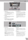
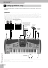
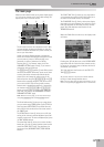
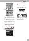
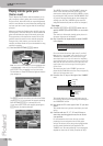
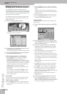
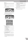
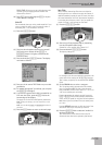
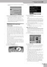
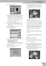
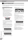
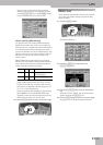
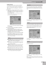
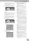
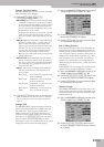
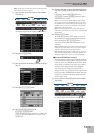
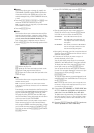
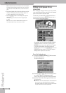
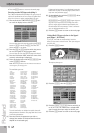
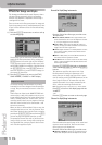
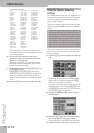
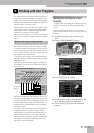
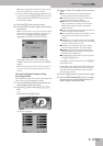
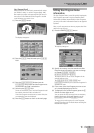
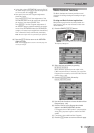
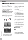
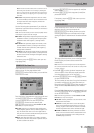
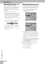
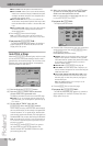
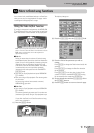
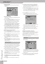
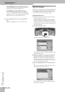
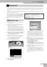
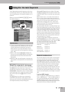
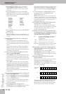
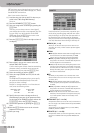
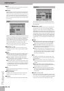
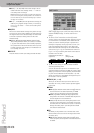
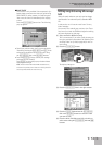
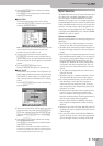
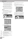
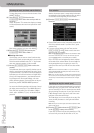
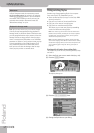
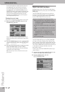
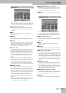
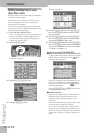
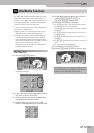
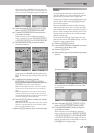
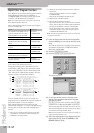
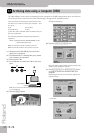
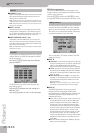
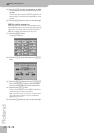
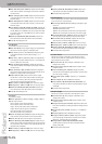
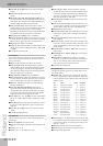
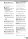
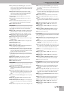
Volume and status of the Style
parts
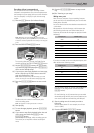
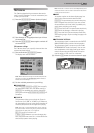
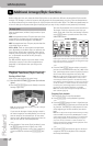
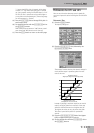
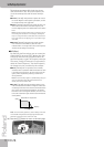
When you press the [STYLE] button below the display,
the following page appears:
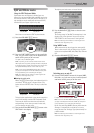
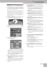
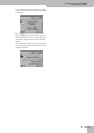
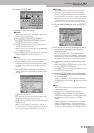
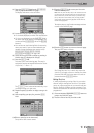
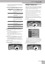
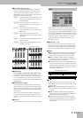
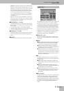
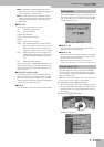
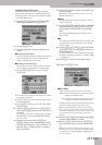
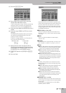
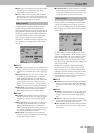
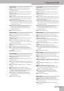
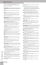
• Start Arranger playback (don’t forget to select the
desired pattern), then press the [SOLO] field of the
Style part you want to listen to in isolation.
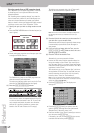
Only one Style part can be soloed. Pressing another
[SOLO] field causes the corresponding part to be
played back in isolation. This setting cannot be saved:
it is merely meant to help you find the part whose
volume you want to change or that you want to
switch off (see below).
Volume of the HARMONIC BAR parts