Appendix | MFX and IFX types and parameters
260
r
E-80 Music Workstation
● Filter Gain (0~12 [dB])—Amount of boost for the filter
output.
● Modulation Sw (Off, On)—On/off switch for cyclic
change.
● Modulation Wave (TRI, SQR, SIN, SAW1, SAW2)—How
the cutoff frequency will be modulated: TRI: triangle wave,
SQR: square wave, SIN: sine wave, SAW1: sawtooth wave
(upward), SWA2: sawtooth wave (downward)
● Rate [sync] (Hz, Note)—Use this parameter to specify
whether (“Note”) or not (“Hz”) the modulation rate should
be synchronized to the Arranger or Recorder tempo.
Depending on your choice, the setting range of the follow-
ing parameter refers to a speed (Hz) or a note value.
● Rate [Hz] (0.05~10.00Hz)—Rate of modulation.
● Rate [note] (musical notes)—Rate parameters can be set
as a note-value of a tempo if you set the “Sync” parameter
above to “Note”. Specify the value of the desired note.
● Depth (0~127)—Depth of modulation.
● Attack (0~127)—Speed at which the cutoff frequency will
change. This is effective if Modulation Wave is SQR, SAW1
or SAW2.
● Level (0~127)—Output level.
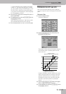
45. Step Filter
This is a filter whose cutoff frequency can be modulated in
steps. You can specify the pattern by which the cutoff fre-
quency will change.
● Step 1~16 (0~127)—Cutoff frequency at each step
● Rate [sync] (Hz, Note)—Use this parameter to specify
whether (“Note”) or not (“Hz”) the rate should be synchro-
nized to the Arranger or Recorder tempo. Depending on
your choice, the setting range of the following parameter
refers to a speed (Hz) or a note value.
● Rate [Hz] (0.05~10.00Hz)—Rate of modulation.
● Rate [note] (musical notes)—Rate parameters can be set
as a note-value of a tempo if you set the “Sync” parameter
above to “Note”. Specify the value of the desired note.
● Attack (0~127)—Speed at which the cutoff frequency
changes between steps.
● Filter Type (LPF, BPF, HPF, NOTCH)—Filter type. Fre-
quency range that will pass through each filter. LPF: fre-
quencies below the cutoff. BPF: frequencies in the region
of the cutoff. HPF: frequencies above the cutoff. NOTCH:
frequencies other than the region of the cutoff.
● Filter Slope (–12, –24, –36 [dB])—Amount of attenuation
per octave: –36dB: extremely steep, –24dB: steep, –12dB:
gentle.
● Filter Resonance (0~127)—Filter resonance level. Increas-
ing this value will emphasize the region near the cutoff
frequency.
● Filter Gain (0~12 [dB])—Amount of boost for the filter
output.
● Level (0~127)—Output level.
46. Humanizer
Adds a vowel character to the sound, making it similar to a
human voice.
● Drive Sw (OFF,ON)—Turns Drive on/off.
● Drive (0~127)—Degree of distortion. Also changes the vol-
ume.
● Vowel 1 (a, e, i, o, u)
● Vowel 2 (a, e, i, o, u)—Selects the vowel.
● Rate [sync] (Hz, Note)—Use this parameter to specify
whether (“Note”) or not (“Hz”) the rate should be synchro-
nized to the Arranger or Recorder tempo. Depending on
your choice, the setting range of the following parameter
refers to a speed (Hz) or a note value.
● Rate [Hz] (0.05~10.00Hz)—Frequency at which the two
vowels switch.
● Rate [note] (musical notes)—Rate parameters can be set
as a note-value of a tempo if you set the “Sync” parameter
above to “Note”. Specify the value of the desired note.
● Depth (0~127)—Effect depth.
● Input Sync Sw (Off, On)—Determines whether the LFO for
switching the vowels is reset by the input signal (ON) or
not (OFF).
● Input Sync Threshold (0~127)—Volume level at which
reset is applied.
● Manual (0~100)—Point at which Vowel 1/2 switch. 49 or
less: Vowel 1 will have a longer duration. 50: Vowel 1 and 2
will be of equal duration. 50 or more: Vowel 2 will have a
longer duration.
● EQ EQ Low Gain (–15dB~0~15dB)—Gain of the low fre-
quency range.
● EQ EQ High Gain (-15dB~0~15dB)—Gain of the high fre-
quency range.
● Panpot (L64~0~63R)—Stereo location of the output
sound. This is a mono effect that combines incoming sig-
nals. You can, however, place the processed signal any-
where between the left and right channels.
● Level (0~127)—Output level.
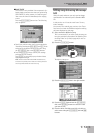
47. Speaker Sim
Simulates the speaker type and mic settings used to record
the speaker sound.
● Speaker Type—Select the type of speaker. The specifica-
tions of each type are as follows. The speaker column indi-
cates the diameter of each speaker unit (in inches) and the
number of units.
● Mic Setting (1, 2, 3)—Adjusts the location of the mic that
is recording the sound of the speaker. This can be adjusted
in three steps, with the mic becoming more distant in the
order of 1, 2 and 3.
● Mic Level (0~127)—Volume of the microphone.
● Direct Level (0~127)—Volume of the direct sound.
● Level (0~127)—Output level.
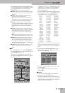
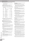
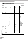
Type Cabinet Speaker Microphone
SMALL 1 small open-back enclosure 10 dynamic mic
SMALL 2 small open-back enclosure 10 dynamic mic
MIDDLE open back enclosure 12 x 1 dynamic mic
JC-120 open back enclosure 12 x 2 dynamic mic
BUILT IN 1 open back enclosure 12 x 2 dynamic mic
BUILT IN 2 open back enclosure 12 x 2 condenser mic
BUILT IN 3 open back enclosure 12 x 2 condenser mic
BUILT IN 4 open back enclosure 12 x 2 condenser mic
BUILT IN 5 open back enclosure 12 x 2 condenser mic
BG STACK 1 sealed enclosure 12 x 4 condenser mic
BG STACK 2 large sealed enclosure 12 x 4 condenser mic
MS STACK 1 large sealed enclosure 12 x 4 condenser mic
MS STACK 2 large sealed enclosure 12 x 4 condenser mic
METAL STACK large double stack 12 x 4 condenser mic
2-STACK large sealed enclosure 12 x 4 condenser mic
3-STACK large sealed enclosure 12 x 4 condenser mic