Panel descriptions
18
r
E-80 Music Workstation
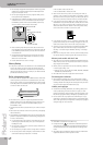
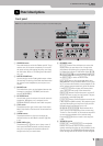
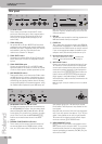
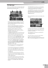
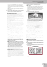
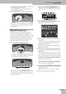
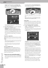
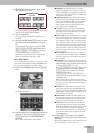
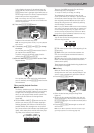
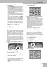
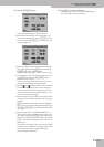
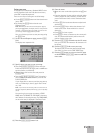
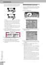
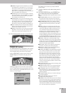
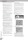
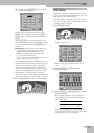
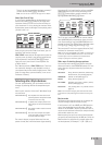
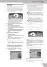
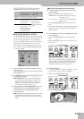
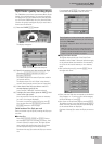
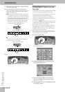
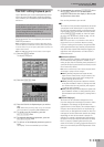
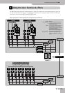
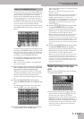
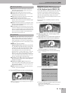
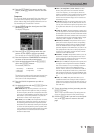
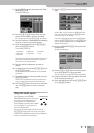
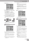
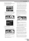
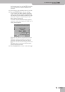
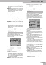
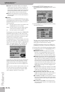
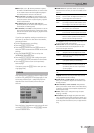
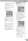
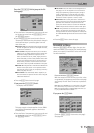
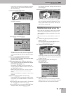
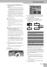
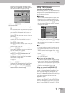
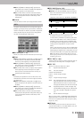
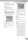
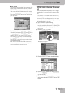
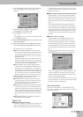
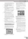
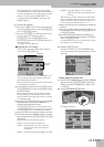
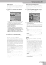
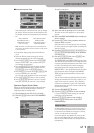
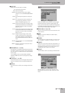
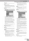
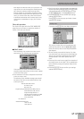
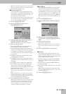
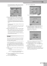
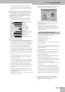
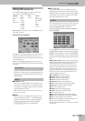
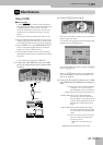
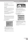
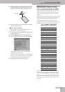
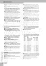
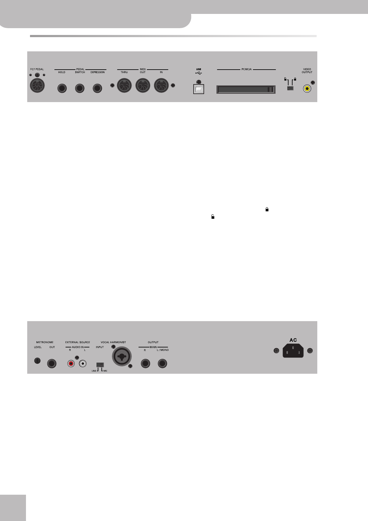
Rear panel
A
FC7 PEDAL socket
This is where you connect an optional FC-7 foot-
switch unit that allows you to start, stop and select
Style divisions by foot. The functions of this foot
switch unit are programmable (and apply to the
entire E-80).
B
PEDAL HOLD socket
An optional DP-2, DP-6, or BOSS FS-5U footswitch
connected to this socket can be used for holding the
Keyboard-part notes. (The Melody Intell part can also
be sustained in this way.) This function is also
referred to as “Sustain” or “Damper”.
C
PEDAL SWITCH socket
Connecting an optional DP-2, DP-6 or FS-5U to this
socket allows you to control an assignable function
by foot.
D
PEDAL EXPRESSION socket
Connect an optional EV-5, EV-7 or BOSS FV-300L
expression pedal to this socket to control the volume
of one or several parts or another parameter by foot.
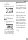
E
MIDI THRU/OUT/IN sockets
These sockets allow you to connect the E-80 to exter-
nal MIDI devices for a variety of applications: receiv-
ing song data in realtime from an external sequencer,
transmitting your playing (and the data of the song
you are playing back) to an external sequencer, using
the E-80 as master keyboard in your MIDI setup, etc.
Note: The MIDI functions can be accessed via the E-80’s Menu
(page 237). Frequently used MIDI settings can be written and
recalled as “MIDI Sets”.
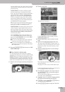
F
USB port
The USB port can be used for archiving purposes and
MIDI data transfer from/to a computer.
G
PCMCIA slot
This is where you can insert a memory card (PCMCIA,
CompactFlash, SmartMedia™ or Microdrive). Memory
cards that are not PCMCIA cards can only be inserted
if you use an appropriate adapter (available at your
computer store). See also the precautions on p. 12.
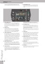
H
Internal memory protect switch
This switch allows you to lock ( , protect) and
unlock ( ) the internal memory. See page 21.
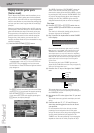
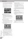
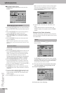
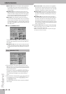
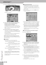
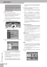
I
VIDEO OUTPUT socket
Connect this socket to the appropriate input of your
TV or monitor. In that case, the lyrics of songs that
contain such information and the note information
extracted in realtime (page 53) will be displayed on
screen even if the [LYRICS&SCORE] button does not
light (in which case the lyrics, chords and notes no
longer appear in the E-80’s display). The VIEWER
information (see p. 56) can also be transmitted to the
external screen.
Note: The signal format (PAL or NTSC) can be set via a MENU
function.
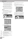
J
METRONOME LEVEL knob and OUT socket
The E-80’s metronome signals can be transmitted to
the METRONOME OUT socket. You can connect head-
phones (Roland RH-300, RH-200, RH-50 or RH-25)
to this socket. This is useful for a drummer, for exam-
ple (as “Click Track”). Use the METRONOME [LEVEL]
knob to set the metronome volume in the head-
phones.
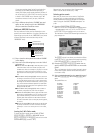
K
EXTERNAL SOURCE/AUDIO IN L/R sockets
This is where you can connect the audio outputs of
an external signal source (CD/MP3 player, synthe-
sizer, etc.). If the source has 1/4” outputs, you either
need adapter plugs (1/4”‰ RCA/Cinch) or Roland
PJ-1M cables. These inputs are only suitable for line-
level signals.
Note that they are stereo (with a left and right chan-
nel). If you only connect one cable to “L” (or “R”), the
signal is only audible on the left (or right) channel.
The volume of the signal received via these inputs
can be set with the D EXT SOURCE knob.
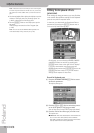
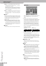
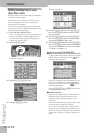
L
VOCAL HARMONIST section
[INPUT] switch: If you connect a microphone to the
INPUT socket, set this switch to “MIC”. To try out the
Vocal Harmonist function for other signals (guitar,
external synthesizers & modules, CDs, MDs, etc.), set
this switch to “LINE”.
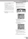
ABCD E F G IH
(left side)
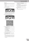
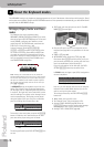
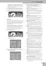
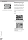
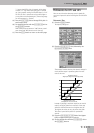
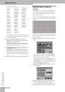
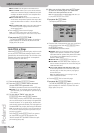
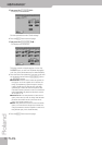
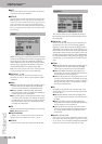
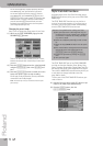
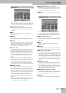
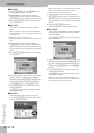
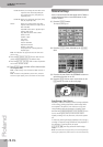
JK L M N
(right side)