


www.ti.com
SRIOFunctionalDescription
Essentially,insteadofthe24-bitvaluerepresentingtheperiodoftheresponsetimer,theperiodisnow
definedasP=(2^24x16)/F.Thismeansthecountdowntimerfrequencyneedstobe44.7–89.5Mhzfor
a6–3secondresponsetimeout.SincetheneededtimerfrequencyisderivedfromtheDMAbusclock
(whichisdevicedependent),thehardwaresupportsaprogrammableconfigurationregisterfieldto
properlyscaletheclockfrequency.ThisconfigurationregisterfieldisdescribedinthePeripheralControl
Register(Addressoffset0x0004).
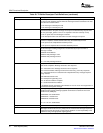
TheCPUinitiatesaTXqueueteardownbywritingtotheTXQueueTeardowncommandregister.
TeardownofaTXqueuewillcausethefollowingactions:
•Nonewmessageswillbesent
•Allmessages(singleandmulti-segment)alreadystartedwillbecompleted
–FailingtocompletethemessageTXwouldleaveanactivereceiverblockedwaitingforthefinal
segmentsuntilthetransactioneventuallytimes-out.
–NotethatnormalTxSMoperationistonotsendanymoresegmentsonceanerrorresponsehas
beenreceivedonanysegment.Soifthereceiverhasbeentorn-down(andisreceivingerror
responses)multi-segmenttransmitwillcompleteassoonasallin-transitsegmentshavebeen
respondedto.
•Whenallin-transitmessages/segmentshavebeenrespondedto,teardownwillbecompletedas
follows:
–Ifthequeueisactive,theteardownbitwillbesetinthenextbufferdescriptorinthequeue.The
peripheralcompletestheteardownprocedurebyclearingtheHDPregister,settingtheCPregister
to0xfffffffC,andissuinganinterruptforthegivenqueue.Theteardowncommandregisterbitis
automaticallyclearedbytheperipheral.
–Ifthequeueisin-active(noadditionalbufferdescriptorsavailable),orbecomesinactiveaftera
messageintransmissioniscompleted,nobufferdescriptorfieldsarewritten.TheHDPregisterand
theCPregisterremainunchanged.Aninterruptisnotissued.Theteardowncommandregisterbit
isautomaticallyclearedbytheperipheral.
–Becauseoftopologydifferencesbetweenflow'sresponse,packetsmayarriveinadifferentorderto
theorderofrequests.
AftertheteardownprocessiscompleteandtheinterruptisservicedbytheCPU,softwaremust
re-initializetheTXqueuetorestartnormaloperation.
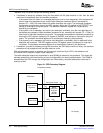
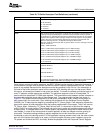
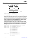
2.3.4.3DetailedDataPathDescription
TheCPPImoduleisthemessagepassingprotocolengineoftheRapidIOperipheral.Messagescontain
applicationspecificdatathatispushedtothereceivingdevicecomparabletoastreamingwrite.Messages
donotcontainreadoperations,butdohaveresponsepackets.
ThedatapathforthismoduleusestheDMAbusastheDMAinterface.Theftypeheaderfieldofthe
receivedRapidIOmessagepacketsaredecodedbythelogicallayeroftheperipheral.OnlyType11and
Type13(transactiontype1)packetsareroutedtothismodule.DataisroutedfromtheprioritybasedRX
FIFOstotheCPPImodule’sdatabufferwithinthesharedbufferpool.Themboxheaderfieldsare
examinedbytheMailBoxMapperblockoftheCPPImodule.Basedonthemailbox,andmessagelength,
thedataisassignedmemoryaddresseswithinmemory.DataistransferredviaDMAbuscommandsto
memoryfromthebufferspaceoftheperipheral.Themaximumbufferspaceshouldaccommodate256Bof
data,asthatisthemaximumpayloadsizeofaRapidIOpacket.Eachmessageinmemorywillbe
representedbyabufferdescriptorinthequeue.
2.3.4.4ResetandPowerDownState
Uponreset,theCPPImodulemustbeconfiguredbytheCPU.TheCPUsetsupthereceiveandtransmit
queuesinmemory.ThentheCPUupdatestheCPPImodulewiththeappropriateRx/TXDMAstatehead
descriptorpointer,sotheperipheralknowswithwhichbufferdescriptoraddresstostart.Additionally,the
CPUmustprovidetheCPPImodulewithinitialbufferdescriptorvaluesforeachdatabuffer.Thisstepis
describedmoreextensivelyinSection2.3.6oftheCPPIspecification.
54SerialRapidIO(SRIO)SPRU976–March2006
SubmitDocumentationFeedback