126
Adding Effects
In Patch mode you can use one multi-effect (MFX), one chorus, and one reverb.
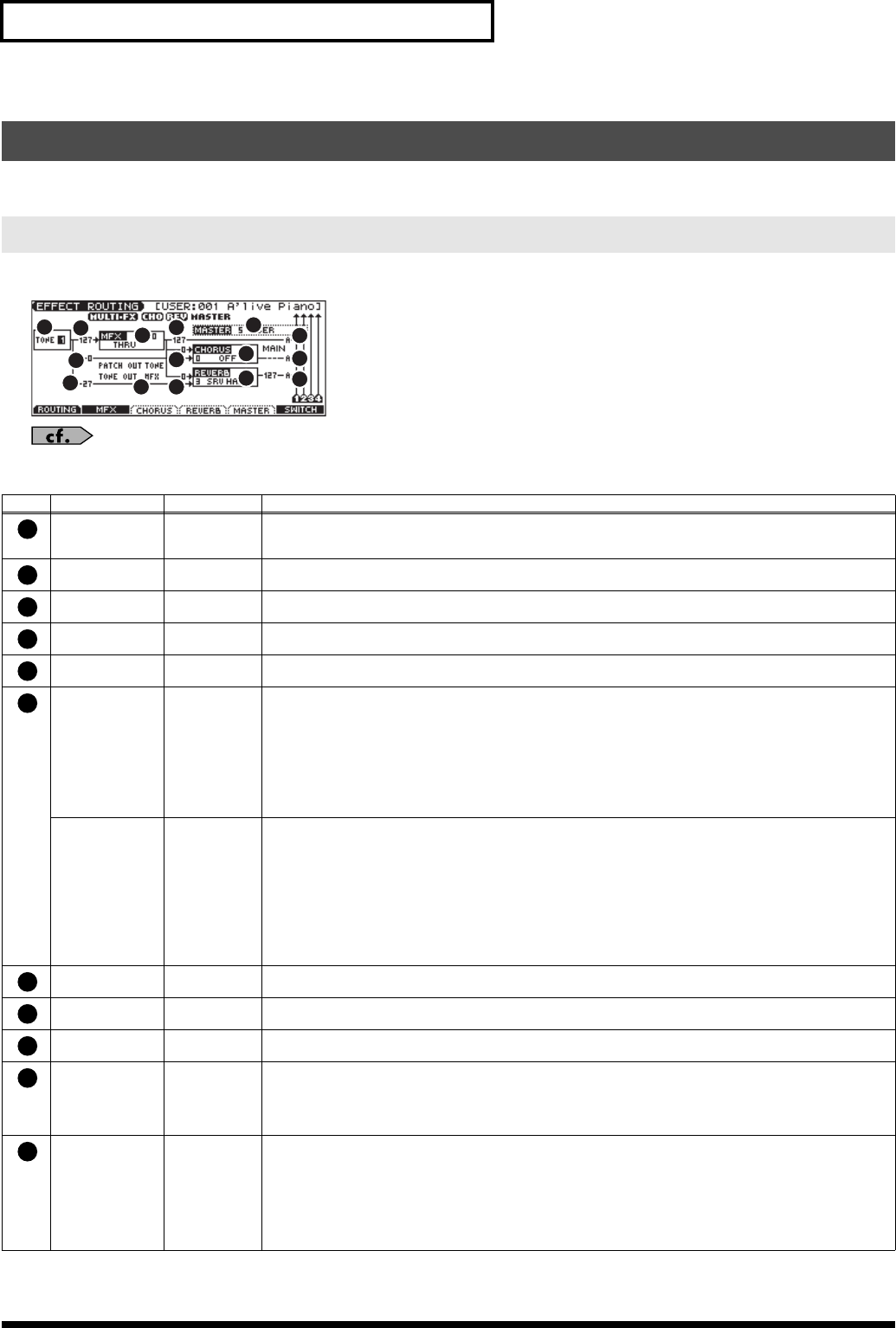
Here you can make overall settings for effects, and the output destination and level of each signal.
fig.Routing
For details on these settings, refer to
Making Effect Settings
(p. 125).
Applying Effects in Patch Mode
Specifying How the Sound Will Be Output (Routing)
Parameter
Value Explanation
Tone Select
(Rhythm Key Se-
lect)
1–4 (A0–C8) Tone (or rhythm tone) for which you want to make settings
This parameter is Rhythm Key Select when a rhythm set is being selected. You can select the rhythm tone (A0–
C8) for which you want to make settings.
Tone Output
Level
0–127 Level of the signal sent to the output destination specified by Output Assign
Tone Chorus
Send Level
0–127 Level of the signal sent to chorus for each tone
Tone Reverb
Send Level
0–127 Level of the signal sent to reverb for each tone
MFX Type 0–78 Selects from among the 78 available multi-effects.
For details on multi-effects parameters, refer to
Multi-Effects Parameters
(p. 131).
Patch Output
Assign
(Rhythm Output
Assign)
MFX,
A, B,
1–4,
TONE
Specifies how the direct sound of each patch will be output.
MFX:
Output in stereo through multi-effects. You can also apply chorus or reverb to the sound that passes
through multi-effects.
A, B:
Output to the OUTPUT A (MIX) jack or OUTPUT B jack in stereo without passing through multi-effects.
1–4:
Output to the INDIVIDUAL 1–4 jacks in mono without passing through multi-effects.
TONE:
Outputs according to the settings for each tone.
This parameter is Rhythm Output Assign when a rhythm set is being selected. You can specifies for each rhythm set
how the direct sound will be output.
* If the Mix/Parallel parameter is set to “MIX,” all sounds are output from the OUTPUT A (MIX) jacks in stereo (p. 158).
Tone Output As-
sign
MFX, A, B, 1–4 Specifies how the direct sound of each tone will be output.
MFX:
Output in stereo through multi-effects. You can also apply chorus or reverb to the sound that passes
through multi-effects.
A, B:
Output to the OUTPUT A (MIX) jack or OUTPUT B jack in stereo without passing through multi-effects.
1–4:
Output to the INDIVIDUAL 1–4 jacks in mono without passing through multi-effects.
* If the Patch Output Assign is set to anything other than “TONE,” these settings will be ignored.
• When the Structure Type parameter has a setting of Type “2”–”10,” the outputs of tones 1 and 2 will be combined
with tone 2, and the outputs of tones 3 and 4 will be combined with tone 4. For this reason, tone 1 will follow the
settings of tone 2, and tone 3 will follow the settings of tone 4 (p. 35).
* If the Mix/Parallel parameter is set to “MIX,” all sounds are output from the OUTPUT A (MIX) jacks in stereo (p. 158).
MFX Output
Level
0–127 Volume of the sound passed through the multi-effects
MFX Chorus
Send Level
0–127 Amount of chorus for the sound passed through multi-effects
MFX Reverb
Send Level
0–127 Amount of reverb for the sound passed through multi-effects
Chorus Type 0–3 Selects either chorus or delay.
0 (OFF):
Neither chorus or delay is used.
1 (CHORUS):
Chorus is used.
2 (DELAY):
Delay is used.
3 (GM2 CHO):
General MIDI 2 chorus
Reverb Type 0–5 Type of reverb
0 (OFF):
Reverb is not used.
1 (REVERB):
Normal reverb
2 (SRV ROOM):
Simulates typical room acoustic reflections.
3 (SRV HALL):
Simulates typical concert hall acoustic reflections.
4 (SRV PLATE):
Simulates a plate reverb, a popular type of artificial reverb unit that derives its sound from the
vibration of a metallic plate.
5 (GM2 REV):
General MIDI 2 reverb
1
2
3
4
5
6
7
8
9
10
11
12
13
14
15
1
2
3
4
5
6
7
8
9
10
11
JUNO-G_e.book 126 ページ 2006年2月13日 月曜日 午後2時44分


